Homemade tram tool

At 1:12 - 1:16 in the 1st video, he shows the calibration procedure. First one indicator is zeroed on the magnet and then the second. When the indicators both read the same, they At this point you are not saying anything about the table and its relationship to the spindle angle; only that when the indicators read the same, the indicator tips lie in a line perpendicular to the spindle axis. The head could be tilted by 10º and the calibration would still be valid as long as the indicator points reference the same point.

The one concern that I have with Tubalcain's calibration is that it doesn't take into consideration any angular runout in his collet, chuck, or however he mounts the spindle square. Edge Technology's method does compensate for any runout.
Also, when he splits the difference in his tramming procedure, he is actually adjusting so both indicators read the same just as done in Edge Technology's video.
 
RJ you are absolutely right that using a two indicator traming tool is both more accurate and quicker than using a single indicator. The error using a two indicator tool is confined to the accuracy of the indicators used. Run out in the spindle/collet is eliminated. When a single indicator is used and rotated run out in the collet/spindle is also added to the error of the indicator. If uncertain after tramming to zero with the two indicator tool rotate the tool 180 deg again and check that as expected both again read zero.
Ron
 
Ron, I don't believe that it is more accurate than mounting an offset indicator in the spindle as has been done for many decades before and here is why.

The error that you have in your tramming adjustment is caused by a stack up of errors. One source of error is the error in reading the indicator. In zeroing the tramming tool you might read the first indicator as .000 but it may actually be .0002. The second indicator might be adjusted to .000 but it may actually be -.0003. Now you move on the the tramming process where you could experience similar errors and they may go in opposite directions. The total error will be the algebraic sum of the individual errors. (for those of you too long out of school, that means consider the direction of the error when adding). In addition, every mechanical device has inherent internal errors (nonlinearity, backlash, etc.) which all factor in. Finally, there is your ability to read the instruments.

So the bottom line is double the number of readings, double the potential error. However, the question is, are the errors associated with reading the tramming tool significant enough to result in an significant error n tramming. IMO, the answer is no. I am confident enough in my ability to set and verify the tram to +/-.001 over a distance of 6" which is good enough for my needs.

The other factor is ease of use. When tramming in the traditional fashion, you determine an offset and make an adjustment to reduce the offset by half. Then you swing the indicator 180º and if your lucky, they now read the same. If not, you repeat the process until they are. The geometry of the mill head is such that rotation of the head through an angle does not produce equal and opposite offsets. With the tramming tool, you're reading both at the same time so you should be able to accomplish the tramming with a single adjustment.

The tramming tool was a simple enough tool to make and the investment was under $30. It has uses other than tramming. You can quickly set up work at an angle to the horizontal in a vise. My tool can work with an offset of 5" and the total differential height can be as much as 2" so I can quickly set angles as large as 20º although not as accurately as using a sine bar.
 
Eh, all that crap is too difficult. Just get it close, torque everything to ludicrous levels, insert a shell mill, then cut the table. If you didn't cheap out on the shell mill and make excessively small cuts you'll be perfect. You should probably square the table/saddle first though.

In all seriousness, at least during my tenure at Haas, they actually had a table cut program for each machine. IIRC, this program was sent to customers on request. Can't remember if a service tech was involved or not though. From my position as a design engineer this seemed exceedingly rare (we would do "specials" from time to time as well). But it may have been more prevalent in the service dept.

---------------------------
IIRC (again: design engineer, not manufacturing or assembly), all squaring was done with an indicator in the spindle (error?) sweeping granite angle slabs or T slots (error?) and then a precision bar (error?) was placed in the spindle (error?) which was then moved up and down while in contact with an indicator affixed somewhere (error?).

^^^^^^^ that's A LOT of potential error going into adjusting a machine that has ±.0005" accuracy and ±.0001" repeatability.

However, these were brand new machines and all the metrology above was calibrated quite often. Plus a ball bar test to confirm everything.


Bottom line, for an old Bridgeport every method discussed so far has it's merits and is perfectly acceptable.

The key point to takeaway here is don't skimp on your metrology gear, have it calibrated at an interval based on use/abuse, and use an accuracy level based on your needs.

Sent from my SM-G900V using Tapatalk
 
RJ
Thanks for the reply. You are correct regarding the summing of errors leading to greater uncertainty. However a general rule for accuracy is to use a measuring instrument an order of magnitude greater than the accuracy required i.e. need to tram to +/- 0.001" then use a tenths indicator. Then the significant error is less than the other errors in the system like Collet /Spindle run out and flex in the column. The dual indicator tool removes the collet runout from the measurement and as you say anyone who has actually used one to tram a mill will know how they really work and make the process much easier. You don't even have to go round the back to read the indicator.
Ron
Yep, I watched someone on U tube build an ER collet on his lathe. He used a .001 indicator and was hoping for less than .001 runnout. Aside from some astute comments on why he failed (like failing to insert a rod in the collet when bluing) , I felt he should have used a .0001 indicator, as when looking to make a tool, you want more accuracy than the part you are looking to create. So many guys shot me down. But when you are looking for .001 or less, using a .001 indicator leads you to +-.0005 error. so a .001 can be .0015, but in his case he was .003 if I remember off. Anyway, when making tooling, I always think finer precision, to help get better accuracy, but the tool must be accurate to begin with.
 
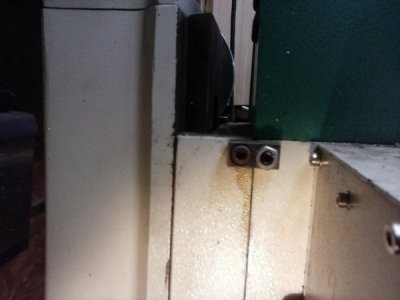
Some of us have installed (on our PM25 type mills) a pair of captive screws, one on either side of the head. When snug they hold it in position, when one is loosened the other can be tightened and adjust the tram of the head.
Any chance on seeing what you did?
I realize they are two different style mills, but it would be interesting seeing what you did.
I envision it like a tailstock with screws to align
 
This is the tramming adjust screw Tom is talking about.


1011152043.jpg
 
Last edited:
The problem I see with a commercial two-dial tram gadget, is that you place it on a surface plate and zero both indicators. This is OK if it's commercial and you trust it. If it's shop made, (if I made it) I wouldn't trust that the spindle that goes in the quill is square with the base which was on the surface plate. Not square and there's no point in starting.
Use one indicator, swing it, and you're good to go.
 
Back
Top