Have no idea what I'm doing, but want to learn!

I ll tell ya what. I like the fact you put yourself out there and want to learn. I guess I am half old grumpy maybe? Doesn t matter I want to help you and would like to encourage you. We are on your side. Maybe we or I need to step up as I am half old and grumpy. You have your life ahead of you and we all would like you to be successful so I thinks it s best to encourage you and throw everything out above and take it all with a grain of salt. I will help you! I ll donate some time and material. Now from you all I ask is to try. Forget cad/cam and your computer for this project. Learn the basic skills. It will make you better at cad/cam. It s much better to struggle to understand something then to just get the answer. When you troubleshoot those basic skills come to surface.

Let s pretend you walk in my shop tomorrow and would like me to (Remember It s a shop that put s food on the table) do some work for you. Don t touch your computer. Were doing this old school. Grab a pencil and a pc. Of paper and do your best to draw a top view and a side view. We ll go from there. I am a mile from the Maine border so no big deal to send it to you.

Put it on paper. Take a pic. And post. We could all help or if you d rather send me a private message but I may learn something too! so how do feel about putting the picture in the thread. You already showed you have courage!

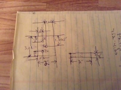
Here is some chicken scratch. A very rough sketch but just to give you an idea. Something like this I can go and cut my material. No math to work out for spacing and depth of cuts. Time cost money.

Well, dang. I was just about to delete myself from this forum because I don’t like being bullied. And here you come along to restore my faith in mankind. Thank you.

I’ve drawn up a drawing, (I’m sorry but it’s in my computer. I feel like I do better with it than doing it by hand) and it’s going to be Mark 1, Revision 0 for this exercise. I know I am going to have to redraw the thing, and I don’t care. I have my back up now, and I’m just not going to let this lack of knowledge and understanding defeat me. I’ve never done that before, and I don’t intend to start now. I promise, the next one will be hand done, as you asked.

I completely agree with you that it’s better to have to work for it than to be given an answer, and I sure wish you’d tell my Calculus teacher that. She writes the problem on the board, and then the answer, and then won’t take any questions. I get told all the time, “You should already know that..." Well hell, lady… How am I supposed to know it if you’re not teaching it? And if I’m already supposed to know it, why am I sitting in this room watching you skip all the steps between the problem and the answer? I hate her. And so does half the class.

So, here’s the first version of my drawing. I think that in the interests of uniformity, and of not having to do extra work by shaving down one of the parts to .25” I’ve changed it to be the same as the other one, at .375” thick. That way, they can be made from the same piece of flat, mild steel bar stock. (See, I’ve been researching this steel materials thing!)

I’m still fuzzy on how to represent the longitudinal grooves, mostly because I don’t know what kind of bits or tools would be used, but I hope I’m right in thinking that you as the machinist, would know that, and all I have to tell you is what they look like. Right?

Others have talked about needing drawings so I won't add to that except to agree that yes, you need a drawing if you want a machinist to talk to you about it.

Tolerances: Not something you worry about with woodworking, but with metalworking it's important. Your half inch hole: Most drills cut slightly oversize. If you use your Forstner bit to drill a half inch hole, it'll be a half inch plus a little. It's not your eyes that can't tell the difference, you probably don't have measuring tools accurate enough (most woodworkers don't). But because that half inch hole is probably a bit oversize, your half inch dowel will slip into it... though it may be a bit tight so you have to tap it in. But wood is forgiving.

Now take a half inch hole in metal. Say you dimension it as such, .500 diameter. Typical hole tolerances might be plus or minus five thousandths (±.005). Say your hole comes in undersize at .495 (.500-.005). You want to put a bolt into it that comes in a bit oversize at .505. No way it's gonna fit even with a BIG hammer. To avoid that, you dimension the hole a bit oversize, a typical drilled hole for a bolt will be 1/64-1/32 (.016-.031) oversize. That's what you need to specify on your drawing, not just 1/2". Going oversize on the holes also allows for the holes being slightly out of position, i.e. if they don't quite line up the bolt will still fit through the overlap area. On the other hand, if you make the holes too oversize, the fit may be too sloppy causing other problems. Since none of us here know what your final intended use is, there's no way we can advise you on what an appropriate fit or tolerance would be. But if you specify too-tight tolerances, it's going to cost you more.

Well, nobody ever managed to get that across to me until now, and it’s something I never understood that the bolt size might be something other than what it says it is. Ignorant stupidity on my part? Just me being naive? That explanation of bolts and their actual measurements, and holes with their measurements really tells me that there are a lot of other details I simply never even thought about, and didn’t think I had to think about. And the worst thing is, all these people on this forum were trying to tell me that I had to worry about this, and I just didn’t see what they were saying. They were all saying this, plainly and right out in the open, and I just didn't see it.

I owe some people an apology for being a jerk about it. Thank you for taking the time to explain it in a way that I could understand it. And I hate Calculus even more now, because that witch could take ten seconds to turn the light on for half the class like you did. We’re trying to teach ourselves how to do it because she won’t.

From what I’ve seen in my research, I don’t have to use a 3/8” bolt. I could use a 7/16” bolt at .452” shank diameter, and still put it through a .50” hole, if the hole is specified to be that at a minimum. The company webpage I looked at states “All dimensions are maximum, with +/-.005” tolerance. If I’m right, that means the maximum shank diameter could be .457” and the minimum could be .447”

Now I see where tolerances come into play. Making things out of wood, well, the tools already take all of this into account, don’t they?

Geez, I feel like a total moron now. Everyone, I really apologize for being a typical know it all on this one. Wow, was I wrong. I apologize. I’ll shut up now and listen to the people who know more. That’s why I came here.

So if I say a 1/2“ hole, with +/- .01” then the hole will be somewhere between .490” and .510” right? Because .457" is still smaller than .490” with room to spare. And there won’t be much wiggle room, the way I have the overall final “thing” in mind. It will be enough. It should work perfectly. I think. And even if the 7/16" bolt is too big, I can always fall back on a 3/8" bolt. It'll fit no matter what.

So, without further babbling on my part, here’s Mark 1, Revision 0.

Thanks.
 

Attachments

  • Tool-01.pdf
    795.5 KB · Views: 32
@Scootered, apology accepted :) And I'm a grumpy old man who has been making metal chips for over 50 years.

Guys, let's see if we can help him through this.

@hman provided a perfectly good sample of a drawing that would suffice if you brought it into my shop. I might have a couple questions. I haven't looked at your updated drawing.

@Scootered, it sounds like you have some woodworking tools, metal working tools are not that much different, you just run them slower. Drilling a 1/2 inch hole in a piece of wood with a Forstner bit will give you a pretty accurate hole..... for wood. But you can't use a Forstner bit in metal because the bit would be destroyed, the cutting geometry is all wrong , so you are stuck with common twist drills until you get into some of the high end speciality drill bits. But for your application a common twist drill will work fine. Anything from the local hardware store would work for this project.

Given that you have some basic tools available, it might be time to set down with a hacksaw, a vice, a file or two, and a drill press or hand drill and make the parts you want. That's the way I would have done this project when I was your age and had very limited tools to work with. Getting the job done with the tools that you have will challenge your creativity.

Not knowing the application, I'm not able to offer any advice on steel alloy to use.

If you don't already own 6'' digital calipers, you can get them at Harbor Freight for about $20. Not the best, but they are pretty accurate. Really helpful in both metal and wood work. https://www.harborfreight.com/catalogsearch/result/index/?dir=asc&order=EAScore,f,EAFeatured+Weight,f,Sale+Rank,f&q=digital+caliper

For now I'll be looking forward to seeing some pictures of your project as you progress.
 
Last edited:
Mark 1, Revision 0 drawing looks pretty good, and complete. Didn't check it thoroughly, but I do have a couple suggestions ...

(1) ]In one place, you call out the material as ¼" bar, in another ⅜". From the apparent thicknesses of the 3D views, I'd have thought that the flat bottom one was going to be ¼" thick, and the rounded one ⅜".
(2) The cross section of it welded to the pipe is not really necessary. If you want to include it, you might want to add a note that it's just for illustration purposes.
(3)Just for clarity's sake, I'd suggest rearranging the 3D views, so that the curved bottom part's views are together, and near to the appropriate end view (possibly moved, so it's above the bottom view showing the holes). Likewise for the flat bottom part. Then note somewhere that you'll need one of each type.

I think you've got the right basic idea. Now it's just a matter of fine tuning.

PS - Looks like you figgered out how to produce the 2D dimensioned views with Paint Shop! I'm a Mac user, so I had no idea that you could do that. Good for you!
 
@Scootered, apology accepted :) And I'm a grumpy old man who has been making metal chips for over 50 years.

Guys, let's see if we can help him through this.

@hman provided a perfectly good sample of a drawing that would suffice if you brought it into my shop. I might have a couple questions. I haven't looked at your updated drawing.

@Scootered, it sounds like you have some woodworking tools, metal working tools are not that much different, you just run them slower. Drilling a 1/2 inch hole in a piece of wood with a Forstner bit will give you a pretty accurate hole..... for wood. But you can't use a Forstner bit in metal because the bit would be destroyed, the cutting geometry is all wrong , so you are stuck with common twist drills until you get into some of the high end speciality drill bits. But for your application a common twist drill will work fine. Anything from the local hardware store would work for this project.

Given that you have some basic tools available, it might be time to set down with a hacksaw, a vice, a file or two, and a drill press or hand drill and make the parts you want. That's the way I would have done this project when I was your age and had very limited tools to work with. Getting the job done with the tools that you have will challenge your creativity.

Not knowing the application, I'm not able to offer any advice on steel alloy to use.

If you don't already own 6'' digital calipers, you can get them at Harbor Freight for about $20. Not the best, but they are pretty accurate. Really helpful in both metal and wood work. https://www.harborfreight.com/catalogsearch/result/index/?dir=asc&order=EAScore,f,EAFeatured+Weight,f,Sale+Rank,f&q=digital+caliper

For now I'll be looking forward to seeing some pictures of your project as you progress.

Okay, not as difficult as I originally thought it might be. I tend to get pessimistic when I'm outside my comfort zone or knowledge area.

Might take a heck of a lot more elbow grease than I originally thought too. I hear they have a sale on that at Tractor Supply, so I might go see if they have some in stock. :cool:

Can't do anything except plan until the weekend, so I've got a lot of "figgerin" to do.

Thanks!
 
Mark 1, Revision 0 drawing looks pretty good, and complete. Didn't check it thoroughly, but I do have a couple suggestions ...

(1) ]In one place, you call out the material as ¼" bar, in another ⅜". From the apparent thicknesses of the 3D views, I'd have thought that the flat bottom one was going to be ¼" thick, and the rounded one ⅜".
(2) The cross section of it welded to the pipe is not really necessary. If you want to include it, you might want to add a note that it's just for illustration purposes.
(3)Just for clarity's sake, I'd suggest rearranging the 3D views, so that the curved bottom part's views are together, and near to the appropriate end view (possibly moved, so it's above the bottom view showing the holes). Likewise for the flat bottom part. Then note somewhere that you'll need one of each type.

I think you've got the right basic idea. Now it's just a matter of fine tuning.

PS - Looks like you figgered out how to produce the 2D dimensioned views with Paint Shop! I'm a Mac user, so I had no idea that you could do that. Good for you!

Yeah, I thought about it and realized it would be better if they were both 3/8" bar, so there wouldn't be any metal removal that wasn't absolutely necessary. My big thing is getting those longitudinal grooves done.

The cross section view is just so people here can see where the weld goes. The rest is a great idea. Thanks!

The version of Paint Shop Pro that I have came off a computer that was originally running Windows95, so I copied over a couple of files to the registry on my Win10 and it runs just fine. The date on the "about" is 1998, which is pretty old for software.
 
Just thought of something ...

If you're not concerned about the finish on the bottoms or sides of the bars, you can add (Stock) to the thickness and width dimensions. That way the machinist knows he can use raw bar stock [I think that 1" x ⅜" is a stock size - could be wrong.] If finish is important, not he would have to machine down from larger stock. The difference in the cost of material is very minor, compared to machining time.

"The version of Paint Shop Pro that I have came off a computer that was originally running Windows95, so I copied over a couple of files to the registry on my Win10 and it runs just fine." ... Yup! And here's a great example of what's probably a generational difference. I've used lots of computers and operating systems, but never even tried to mess with anything like registry files. You definitely have me beat there!
 
Here is what I would do if I were 15 and in your shoes;

Get some flat metal stock that matches your pipe material so it can be welded, I.e. if the pipe is steel, than get steel flat stock. If the pipe is aluminum, get aluminum flat stock,

Find some files, get a round one, flat one and square one. Craigslist is good for this.

Find a Hacksaw,

Find a drill press,

Find a set of calipers,

Find a bench vise,

Get some layout fluid(dykem) if that doesn’t suit you, get a sharpie,

Start laying out your grooves using your calipers in the layout fluid, file grooves by following the lines,

Layout the radius on both ends using your calipers in the layout fluid and file until you are satisfied with the fit in the pipe,

Drill the holes,

I’m not inclined to go back nearly 80 posts at this point, but it looks like you may have had counterbores as well. You will need to buy and end mil of appropriate size (or counterbore) if that is the case.

For what it’s worth, I would skip the pipe radius form and just file out a shallow angle for the clamp to sit on the pipe for welding purposes. But this is personal preference and would potentially make filing easier that’s all.

If this is for clamping for parts you may want to consider hardening and tempering the grooves once you are finished so they are tough enough to endure whatever you are planning to subject them too. For example, if you plan on clamping wood and use steel for these jaws, then hardening probably isn’t necessary, but if you plan on clamping other steel parts, you might consider heat treating them. Research YouTube for that and come back here for more questions.

You can build this! Good luck and welcome to the forum!


Sent from my iPhone using Tapatalk
 
Scootered! Glad to see you here on this forum today! You came here to learn and you asked questions. Sometimes there is more to the question or the answer. Your at an age now where your train of thought will carry you the rest of your life. Don t stop asking questions no matter if you annoy people. I too struggled in the beginning. My first five years in my apprentiship was a struggle. I worked in what is called a Screw Machine Shop and there was no Apprentiship program so I was very fortunate enough to have my employer enlist me in the General Machinist Program. There both machining but very different and like I mentioned in an earlier post the process is completly different. The others in the course worked on similar machines all day. I new I Was behind so I threw my pride out the window and let them all know so I could hound them. By The third year some were taking me aside when they did something at work I wouldn t t be exposed to. I Applied myself and managed to get my license. Now at 51 those days in those screw machine shops have taught me so much about tooling that others may not know but there are still things maybe I Should know or do better as a General machinist. I am like you I still ask, and I do know at times I annoy people. Even here. I Don t mean to. It s just me being who I am and honest and maybe not think like I should. My ipad. Keeps messing with sorry about the edits.
My point is this. Don t rely on aids like cad cam and your computer. Learn the understanding behind all that. Learn to work things out on paper with your pencil and calculator. You are going to struggle and may think you are getting behind. A light will,go,off at some point and you will leap frog all those that relied on there aids like cad amd cam. The world isn t perfect and when you can trouble shoot because you know those formulas and work it out on paper you will be top dog. No one will control you. You will be wanted and needed. Take advantage and you will be very successful in life. Believe in yourself, sometimes that is all you will have.
 
Last edited:
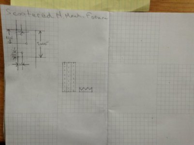
I posted a sketch yesterday messy for a reason and some dimensions to get you to think like a machinist. I made the same top view on graph paper and neat. If you came to me with this at your age I would shut my machines off and make time for you. It would impress me like you have asking questions.
We talked about tolerances and decimals represent a tolerance unless it is stated. So 1" is more like carpentry with plus or minus .010". Machinist divide one inch by 1000. So think of an inch as 1000 thousands. 1/2 " would be 500 thousands of an inch. We write that as .500" or could be .5". or .50". A specific feature like a hole that may need to be tight could have it s tolerance written at that hole on the drawing of something like plus or minus .002"
My drawing has a centre hole from one edge at a distance from the edge at 1.500". The length of the pc. Is not 3 inches but 3.01". The hole itself is a 1/4 inch hole. If I made that length at 3.01" and was sloppy because the tolerance of just two decimal places allows me to be plus or minus .005". and made that length at 3.14". I could only drill that hole in the right position if I measured from the the edge as the drawing shows. It looks like the hole is centred but it isn t. The customer needs that hole at 1.500" from that edge. Your half inch or one of your holes you mentioned had a tolerance of I think it was plus or minus .015". Now if you drill all your holes and you happen to come across a drill that is at the extreme of that tolerance on the minus side will your half inch bolt fit?
For some reason I can t pull up your attachment. Is there a chance you could put pencil to paper. Get yourself some graph paper and keep a shop Note book you can draw on, do your math and I cant stress this enough write down and go through your order of operations. We overthink everything just to be sure. It will save you time and and keep scrap to a minumum.
Here are the pics one is of yesterdays top view and the other two is somewhat of your part. Top view and side view. It helps visualize the part.
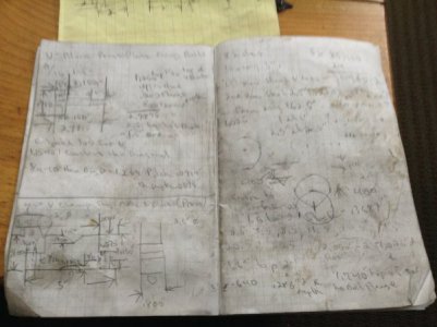
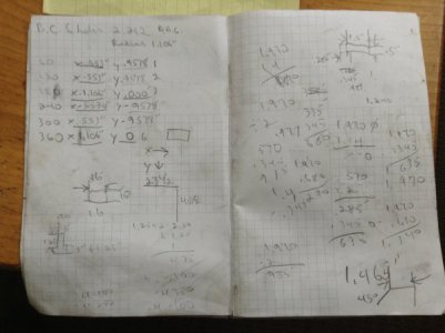
This is my scribble book. Everything I make gets a drawing and math done beside it. When I am done with it it goes in a box. That way if I Have to repair something of my own I can easily reproduce it exactly. Trig. now is old hat just Like Calculus will be for you one day. Continue on your path to ask questions and don t be afraid to challenge yourself and stumble.
Now your going to not only learn what you have asked but your also going to improve your abilities shop wise and skill. Here is a my all time favourite quote from someone Many may recognize on other forums that goes by the avatar of Wigitmaster. Kind of an oxymoron for a machinist but it makes sense for me and it was like a revelation to me.. Here goes. "Forget about perfection, worry about progress or you ll never get off the ground"
Just ask whatever you need!

image.jpeg

image.jpeg

image.jpeg

image.jpeg
 
Last edited:
Here is what I would do if I were 15 and in your shoes;

Get some flat metal stock that matches your pipe material so it can be welded, I.e. if the pipe is steel, than get steel flat stock. If the pipe is aluminum, get aluminum flat stock,

Find some files, get a round one, flat one and square one. Craigslist is good for this.

Find a Hacksaw,

Find a drill press,

Find a set of calipers,

Find a bench vise,

Get some layout fluid(dykem) if that doesn’t suit you, get a sharpie,

Start laying out your grooves using your calipers in the layout fluid, file grooves by following the lines,

Layout the radius on both ends using your calipers in the layout fluid and file until you are satisfied with the fit in the pipe,

Drill the holes,

I’m not inclined to go back nearly 80 posts at this point, but it looks like you may have had counterbores as well. You will need to buy and end mil of appropriate size (or counterbore) if that is the case.

For what it’s worth, I would skip the pipe radius form and just file out a shallow angle for the clamp to sit on the pipe for welding purposes. But this is personal preference and would potentially make filing easier that’s all.

If this is for clamping for parts you may want to consider hardening and tempering the grooves once you are finished so they are tough enough to endure whatever you are planning to subject them too. For example, if you plan on clamping wood and use steel for these jaws, then hardening probably isn’t necessary, but if you plan on clamping other steel parts, you might consider heat treating them. Research YouTube for that and come back here for more questions.

You can build this! Good luck and welcome to the forum!


Sent from my iPhone using Tapatalk

I didn't look at your final dimensions, but if possible I would use u channel that matches your pipe if possible to make fit up to the pipe and welding easier (less warp too), otherwise agree with vtcnc
 
Back
Top