Has anyone replaced the feed nut for the X and Y axis on the PM 833 T

ltlvt

H-M Supporter - Sustaining Member
H-M Platinum Supporter
Joined
Aug 29, 2019
Messages
522
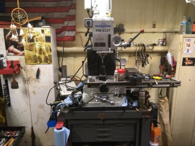
Suddenly I have all kinds of slop in the X and Y table on the mill. Even with the locks in place when I was milling a part using a 1/2" 2 flute end mill the table would move. With the locks released I tried to move the table by pushing on it and shaking it by hand and do not see any significant movement, but I verified the slack with a dial indicator on the spindle. The spindle has less that .0005 run out with a half inch collet I bought from Quality machine when I bought the mill and a 1/2" dowel pin. So the spindle is not the problem but with the indicator tip touching the dowel pin and turning the X or Y crank by hand there is at least .100 thou before the indicator moves at all. I downloaded the PDF file from Precision Mathews, but the pictures are generic. So any detailed Assy drawings or tutorial would be awesome. I bought the mill new so if there is damage I only have Me to blame.

Thanks in advance

 
Last edited:
If the table locks are on and something is moving it wouldn’t be too much slop in the feed screw or nuts. Normally you can tell the wear by how much back lash there is. I would start looking to see if something is loose on the head mounting or column
 
I was wrong about not being able to move it by pushing on it. I took the X-axis screw out tonight and now I can see the mounting socket head cap screws are either loose or sheared. Tomorrow I will slide the table to the right farther so I can get at the cap screws and go from there. The lead screw is in perfect condition. I am trying to document with pictures and short clips as I go for future reference so others that may need it can understand how it comes apart and goes together.


Attachments

  • IMG_2596.JPG
    IMG_2596.JPG
    577.3 KB · Views: 21
  • IMG_2595.JPG
    IMG_2595.JPG
    484.6 KB · Views: 23
Got the mill back together today and all seems well. I did pull the cap screws back out one at a time and put some blue Loctite on them. When I say it is labor intensive it is because I had to remove the DRO and there is very little room to get around the mill. Other than that it is simply remove the end bearing caps on both ends of the lead screw and then unscrew the lead screw. You could probably do the job without removing the lead screw from the machine, but I did it for inspection purposes. The screw and nut were in great shape. The important thing is of course Safety. I put a bottle jack under the right side of the table because I did all the work from the left side. Once you remove the Gib it will give you the extra room to shove the table far enough to the right to get to the nut and the cap screws. Extending it that far to the right makes the table somewhat dangerously close to falling off without the jack. So, if attempting this job put a plan together in advance. You will be glad you did.

Also worth pointing out is the smashed lube lines. This must have happened on ASSY at the factory because I have never and never will run the table that far to either end. I will and have loosened the vice and moved it and dialed it back in whenever necessary to gain more travel. I also have a BP Clone that has the 52-inch table so any excessive long jobs will be done on it anyway.

If I had new lube lines to replace the smashed ones I would replace them but since it was a factory add on it is unlikely to be a replacement part number for the lines. If so I would love to have the information so I can order replacement tube and ferals. I expect the nuts for the lines to be okay. . So enough of my Tabbling . (Babbling via Keyboard)

 
Back
Top