- Joined
- Feb 7, 2013
- Messages
- 792
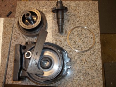
Hi I have a Grizzly H5940 Rotary Table that I received as a gift and there was no way I was going to return it so after reading several complaints about this table I decided to tear the table down and go through it to make it work. I could go way over board and bore it install timken bearings but I think it would be better to fix what is there so anyone can make it work good.
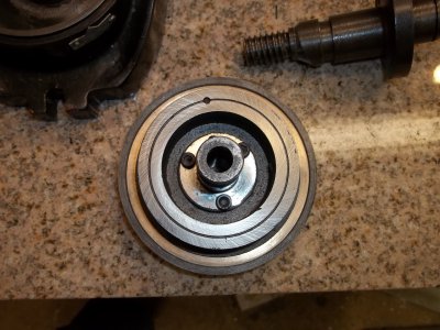
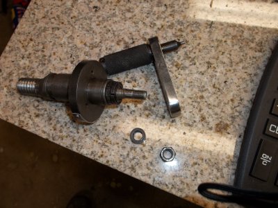
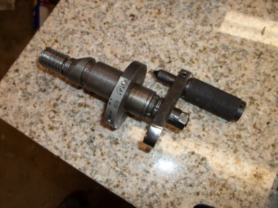
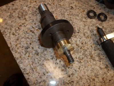
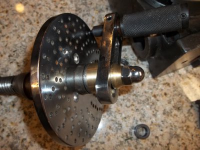
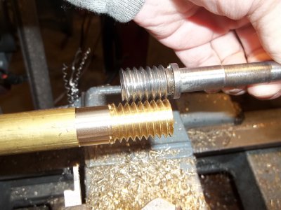
The first thing I noticed on the tear down that the steel and cast iron parts are pretty good with some and I do mean Some nice machine work but most of that is cosmetic. The table has no ball or timken bearings in it at all that is OK there seems to be plenty of thrust surface but no brass thrust washers or anything like that. My first concern was when the worm gear is on an excentric so it can be realeased so the table will free wheel that is great as long as when the worm mates with the gear and they line up this one does not the worm gear is to low and the only way to change this is to lower the table and gear assembly. The second problem appeared to be the worm gear looks like it was dropped on the floor from the factory and a couple teeth where slightly damaged along with all the casting sand inside and a lack of grease things where looking dim.
I started by dressing the worm gear the gear is about as hard as my mother in laws heart and a file would barely touch it but I finally got it cleaned up. I then took the housing to the mill and set it up to cut out the lower thrust surface to get better gear alignment. I remove 25 thousands and then I went to lap in the table thrust surface but I did not want to remove any material from the table thrust surface. It was nice and straight with the surface of the table so I use some spray on adhesive and stuck a piece of 400 wet/dry sand paper to the bottom dropped the table back inside the housing and with a drill I lapped in the surface checked it with some blue dye and it turn out shinny and perfect.
After I cleaned everything up I reassembled the table back into the housing reinstalled the worm gear and presto!! smooth as can be. Now it is almost impossible to measure the gear height of the worm without xray vision but as close as I can measure it is in pretty close alignment with the main gear maybe someday I will make a new worm gear for it that is slightly larger in dia. that way the excentric will not have to roll over as far and pull it off center.
Now I cannot reassemble because I want to take some pictures and for the bottom thrust I ordered a needle type thrust bearing the stock method was almost laughable and I will make some changes to the locking devices as well. That is all for tonight the thrust bearing should be here tomorrow and I also going to create a thrust surface up close to the table for more stability.. Ray
Last edited:


