Which includes the overload block which is wired back into the contactor pickup coil. There can be auxiliary NCNO switches that operate mechanically with the engagement of the contacts.
Things can look complicated but are usually just lots of simple function parts connected together.
The wiring diagrams for my industrial edgebander cover many pages, all in Italian!
Sir, I would beg to disagree with you. A contactor does
not include an overload deck. When you add the overload deck, a contactor
becomes a starter. A circuit breaker is not the same as an overload. A circuit breaker protects against high current, an overload protects motors and the like that have high inrush current at startup.
Your description of relays vs contactors is otherwise pretty close on point. I personally take the position than a contactor is just a very large relay, being used for power handling where a relay is to switch control circuits. That description is not a hard and fast rule. I have worked on circuits where the relays were (physically) much larger than a "normal" contactor. It is really dependant on the type of circuits being dealt with.
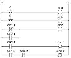
To the OP, I agree that wiring diagrams are one step above useless. I'll take a ladder diagram any time. I have done many ladder prints for industrial (DC) cranes, as well as machine controls. I
might could make a ladder diagram had I the wiring diagram for your machine. But it would be a slow process at best as I have had one too many strokes and been retired for many years. But I do agree with other posters that a ladder diagram is much more suitable for troubleshooting. The wiring diagram is for the assembly floor, not practical use.
For what it's worth, I have worked with German (Dutch?) language logic prints, both relay and symbolic. The language is irrelevant, the symbology is what matters. Relay logic is a world of its' own. I lay claim to speaking three languages: English, Electrical, and Computers, not WinDoze, but how a computer works.
.