Please let me know what you think of this and if you try it out! Good or bad? Useful or not? A waste of my time? I look forward to hearing your suggestions, improvements and especially any questions. It would be nice to hear if others have done similar work.
Here I am sharing my efforts to automate some Gcode generation via the use of a Excel Workbook (multiple spread sheets). A quick Web search did not provide much useful to me about how others might do this. Anyway, I always wanted to know more about Excel Macros so I used it as an excuse to teach myself "some" MS Visual Basics for Applications.
(Technical Disclosure: My PC is set up with Microsoft Win 7-64bit, and I run Office 2010. Also my CNC mill runs from Mach3 so the Gcode is written for Mach3. However, the Gcode functions are pretty simple and so it will probably run on other CNC platforms. The Excel Workbook uses Macros, so even if you are afraid of malware in them, you can see what the program is doing without using them. Maybe I will even post one version of the workbook where they have been removed into a separate text file.)
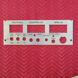
Back Ground: Many folks use a CAD package to draw their work and then rely on the program to generate Gcode. When the results are generated the code is not very intuitive and depending upon the work complexity can be quite long. However, if you want to change something about the device it commonly requires a lot of time to do make the changes. This becomes more tedious the more complex the drawing. This is probably true even for planar objects such as cutting various holes in a sheet, like that of an instrument panel
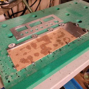
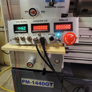
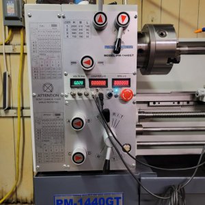
I have been writing Gcode for things like this "by hand" for a while and recently made an instrument panel for my VFD converted PM1440GT lathe. (It is always a learning experience.) Then I found that I had wished I had laid out the instrument differently with switches, displays, lights in different locations. So I did it over! Then I decided I would actually like to add a digital counter display and switch to the panel and was faced with repeating the work again. The Thread on my conversion and the instrument panel installed in the lathe is HERE https://www.hobby-machinist.com/thr...tronic-components-pm1440gt-vfd-3-phase.95058/:
Later, I will post more about my Gcode generated Instrument Panel there.
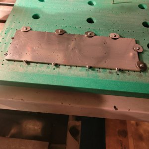
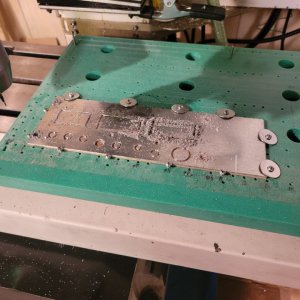
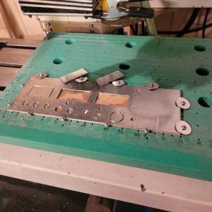
What is in the Posting?: So this time I wrote a program in Excel to generate the Gcode. Excel inputs include the device style (switch, display, light, etc.) size, location, orientation, and features like detailed shape features and cutting tabs to prevent tear-out during the machining. In addition, things like tool diameter, i.e. tool offset, as well as multi-path cuts to adjust the depth of the feed requires calculations. The final depth of the cut should coincide with the bottom of the sheet to prevent excessive cutting into a backer board. As long as one is doing those calculations you might as well add in the feature that the plate or backer board is not level or flat. Depending upon the device shape detail this required math calculations to determine the points along tool path where the Gcode needs to change.
So I have written an Excel workbook which will automatically generate the Gcode for you, if you are willing to invest just a little bit of time to input data. It generates Gcode for any number of circles and rectangles at user specified locations, sizes, features etc. It does this by using templates for a shape where the user inputs parameters into a table and then executes macro(s) that generates the code. There are is a Circle and a Rectangle Template spread sheet so far, but there can be others that a user might decide to build. They are each a template from which other sheets of similar styled devices are generated via substituting feature parameters, so the instrument panel can have lots of different featured device holes.
Realizing, that using even a spread sheet to compose Gcode maybe a new approach, lot to comprehend, for some folks (It was for me!) I will post two entries. The first posting will be of two individual spreadsheet programs which composes the Gcode for either a single rectangular or singular circular device with various edge features. The second posting will be of the multi-spread sheet workbook where Gcode from the individual device templates can be used to compile a large set of devices into a single set of Gcode.
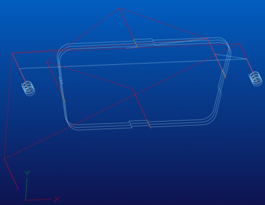
This first posting of the Rectangle (uwRectT) and Circle (uwCirT) templates has specific device parameters (which you can change) already written into the spread sheets. This will allow one to perhaps understand how my Gcode is constructed. There is a uwReadme sheet in the spread sheets which I started to draft for the overall Workbook. If you read the portion under these template names it may provide insight into what the individual spreadsheets actually do. However, if you want to get a general idea of the individual spread sheet functions you can just copy and paste a bit from these two template sheets into a Gcode simulator or you CNC tool and see the tool path. You do not have to run the program with macros to do this. Copy the column from the RED cell (~row 197 column on the right) containing "(G-code-- copy and paste into Simulator i.e. Mill Wizard)" to the bottom of this column where the cell contains "%****************". Then paste!
Five files are available here, but the SingleRectHole may be easier to understand as it has fewer features:
1) SingleRectHole LC26_1100.xlsm Zip This contains the simple Macro for copying the Gcode. "Cntrl+Shift+O" will invoke the macro.
2) SingleRectHole LC26_1100.xlsx This has NO Macros.
3) SingleCircleHole LC26_1100.xlsm Zip This contains the simple Macro for copying the Gcode.
4) SingleCircleHole LC26_1100.xlsx This has NO Macros.
5) Module6.bas Zip This is the Macro as a text file. If you change the .bas to .txt you will be able to open it.
HM did not accept .xlsm files nor .bas files so I had to zip these.
The next Post will contain and provide a bit more detail about the MAIN program.
Here I am sharing my efforts to automate some Gcode generation via the use of a Excel Workbook (multiple spread sheets). A quick Web search did not provide much useful to me about how others might do this. Anyway, I always wanted to know more about Excel Macros so I used it as an excuse to teach myself "some" MS Visual Basics for Applications.
(Technical Disclosure: My PC is set up with Microsoft Win 7-64bit, and I run Office 2010. Also my CNC mill runs from Mach3 so the Gcode is written for Mach3. However, the Gcode functions are pretty simple and so it will probably run on other CNC platforms. The Excel Workbook uses Macros, so even if you are afraid of malware in them, you can see what the program is doing without using them. Maybe I will even post one version of the workbook where they have been removed into a separate text file.)
Back Ground: Many folks use a CAD package to draw their work and then rely on the program to generate Gcode. When the results are generated the code is not very intuitive and depending upon the work complexity can be quite long. However, if you want to change something about the device it commonly requires a lot of time to do make the changes. This becomes more tedious the more complex the drawing. This is probably true even for planar objects such as cutting various holes in a sheet, like that of an instrument panel
I have been writing Gcode for things like this "by hand" for a while and recently made an instrument panel for my VFD converted PM1440GT lathe. (It is always a learning experience.) Then I found that I had wished I had laid out the instrument differently with switches, displays, lights in different locations. So I did it over! Then I decided I would actually like to add a digital counter display and switch to the panel and was faced with repeating the work again. The Thread on my conversion and the instrument panel installed in the lathe is HERE https://www.hobby-machinist.com/thr...tronic-components-pm1440gt-vfd-3-phase.95058/:
VFD conversion using solid state electronic components.
Later, I will post more about my Gcode generated Instrument Panel there.
What is in the Posting?: So this time I wrote a program in Excel to generate the Gcode. Excel inputs include the device style (switch, display, light, etc.) size, location, orientation, and features like detailed shape features and cutting tabs to prevent tear-out during the machining. In addition, things like tool diameter, i.e. tool offset, as well as multi-path cuts to adjust the depth of the feed requires calculations. The final depth of the cut should coincide with the bottom of the sheet to prevent excessive cutting into a backer board. As long as one is doing those calculations you might as well add in the feature that the plate or backer board is not level or flat. Depending upon the device shape detail this required math calculations to determine the points along tool path where the Gcode needs to change.
So I have written an Excel workbook which will automatically generate the Gcode for you, if you are willing to invest just a little bit of time to input data. It generates Gcode for any number of circles and rectangles at user specified locations, sizes, features etc. It does this by using templates for a shape where the user inputs parameters into a table and then executes macro(s) that generates the code. There are is a Circle and a Rectangle Template spread sheet so far, but there can be others that a user might decide to build. They are each a template from which other sheets of similar styled devices are generated via substituting feature parameters, so the instrument panel can have lots of different featured device holes.
Realizing, that using even a spread sheet to compose Gcode maybe a new approach, lot to comprehend, for some folks (It was for me!) I will post two entries. The first posting will be of two individual spreadsheet programs which composes the Gcode for either a single rectangular or singular circular device with various edge features. The second posting will be of the multi-spread sheet workbook where Gcode from the individual device templates can be used to compile a large set of devices into a single set of Gcode.
This first posting of the Rectangle (uwRectT) and Circle (uwCirT) templates has specific device parameters (which you can change) already written into the spread sheets. This will allow one to perhaps understand how my Gcode is constructed. There is a uwReadme sheet in the spread sheets which I started to draft for the overall Workbook. If you read the portion under these template names it may provide insight into what the individual spreadsheets actually do. However, if you want to get a general idea of the individual spread sheet functions you can just copy and paste a bit from these two template sheets into a Gcode simulator or you CNC tool and see the tool path. You do not have to run the program with macros to do this. Copy the column from the RED cell (~row 197 column on the right) containing "(G-code-- copy and paste into Simulator i.e. Mill Wizard)" to the bottom of this column where the cell contains "%****************". Then paste!
Five files are available here, but the SingleRectHole may be easier to understand as it has fewer features:
1) SingleRectHole LC26_1100.xlsm Zip This contains the simple Macro for copying the Gcode. "Cntrl+Shift+O" will invoke the macro.
2) SingleRectHole LC26_1100.xlsx This has NO Macros.
3) SingleCircleHole LC26_1100.xlsm Zip This contains the simple Macro for copying the Gcode.
4) SingleCircleHole LC26_1100.xlsx This has NO Macros.
5) Module6.bas Zip This is the Macro as a text file. If you change the .bas to .txt you will be able to open it.
HM did not accept .xlsm files nor .bas files so I had to zip these.
The next Post will contain and provide a bit more detail about the MAIN program.