- Joined
- Sep 2, 2023
- Messages
- 2
Hello,
Hi to all, new to the forum....looks fantastic,
My G0704 benchtop mill from 2010 does NOT have a hole in the spindle nose to prevent spindle rotation when tightening the drawbar. I've been living with it, haven't used the mill alot, until recently. Occasionally. in desperation, I use a pair of channellock pliers to grasp the spindle nose. Also tried a rubber strap wrench (slips easily). I see that more recent version G0704 spindles have a hole for a pin. Looks like PM25 has ground flats on the nose.
Any suggestions how I might add a brake feature to the spindle?? I thought about drilling my own hole in the nose, but the spindle material is very hard, I can barely scratch it with a file. I'm sure it would destroy HSS drill bit Don't want to hand grind some flats as 1. it would be ugly, 2. grinding debris might go in bad places like bearings, 3. I would be really ugly.
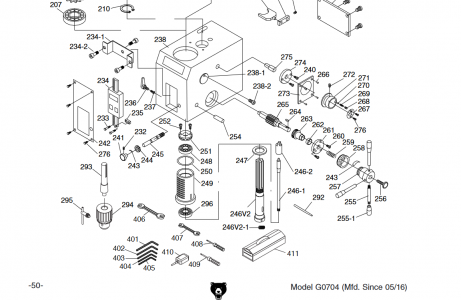
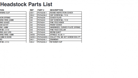
I suppose dissassembling the spindle to remove the part 246V1 (diagram show version2, with factory hole, date 0811) would offer some more opportunities, but that seems like alot of work... but maybe you can convince me that's not such a difficult task
Hi to all, new to the forum....looks fantastic,
My G0704 benchtop mill from 2010 does NOT have a hole in the spindle nose to prevent spindle rotation when tightening the drawbar. I've been living with it, haven't used the mill alot, until recently. Occasionally. in desperation, I use a pair of channellock pliers to grasp the spindle nose. Also tried a rubber strap wrench (slips easily). I see that more recent version G0704 spindles have a hole for a pin. Looks like PM25 has ground flats on the nose.
Any suggestions how I might add a brake feature to the spindle?? I thought about drilling my own hole in the nose, but the spindle material is very hard, I can barely scratch it with a file. I'm sure it would destroy HSS drill bit Don't want to hand grind some flats as 1. it would be ugly, 2. grinding debris might go in bad places like bearings, 3. I would be really ugly.
I suppose dissassembling the spindle to remove the part 246V1 (diagram show version2, with factory hole, date 0811) would offer some more opportunities, but that seems like alot of work...
 but maybe you can convince me that's not such a difficult task

