-
Welcome back Guest! Did you know you can mentor other members here at H-M? If not, please check out our Relaunch of Hobby Machinist Mentoring Program!
You are using an out of date browser. It may not display this or other websites correctly.
You should upgrade or use an alternative browser.
You should upgrade or use an alternative browser.
Flat Head Hit Miss Engine
- Thread starter rogerl
- Start date
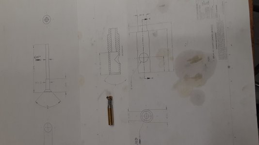
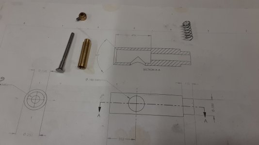
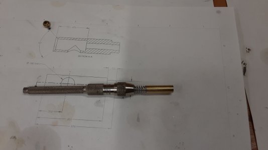
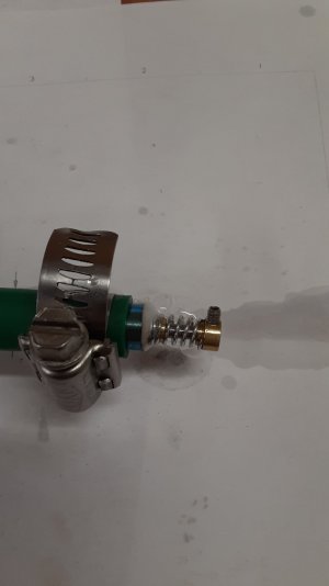
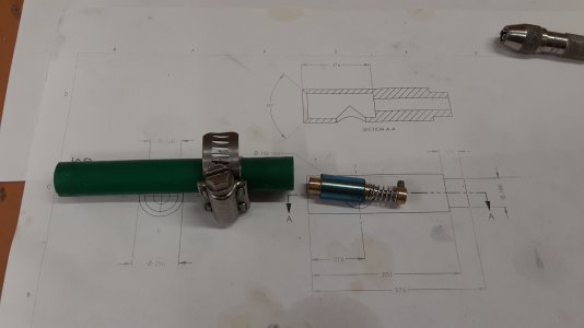
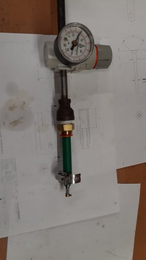
Below are some photos of the design and the test rig. The outer body of the brass is .250". The hole drilled in the brass is .187. The hole for the stem is .109. The valve OD is .250 with a .125 step to the .109 diameter. I used a 90 degree countersink to cut the taper in the brass and a tool bit ground at 45 degrees and aligned to the chuck with a 45 degree block to cut the angle on the valve. I used a Starrett pin vice to grab the end of the valve to lap it in. To test it I put a piece of polyurethane tubing, 1/4" ID 3/8" OD, over the valve body then a piece of 1/2" OD 3/8" ID polyurethane tubing over that and secured it with a breeze clamp. I then hooked it to my regulator set at 40 psi. The bubbles in the photo were taken at 20 psi. At 40 psi it is a constant stream of air coming out around the stem.
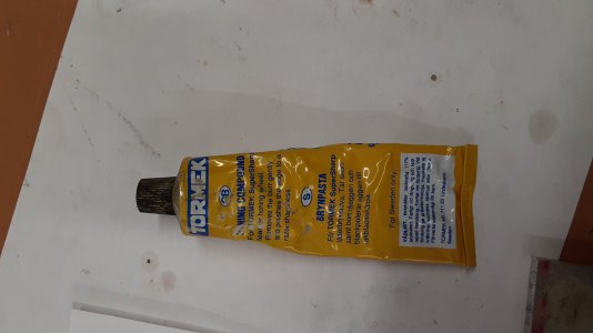
I was using a lapping compound made from 220 grit carbide powder and oil, than 600 grit carbide powder and oil, then the Tormek polishing compound. Under the microscope there were lots of scored lines on the steel and the brass. I tried re-cutting the brass and polishing the steel then using just the Tormek polishing compound and that did no better. What am I doing wrong?
Roger L
Attachments
- Joined
- Feb 2, 2014
- Messages
- 1,208
I don't think you are doing anything wrong but I am concerned that the hose may be leaking around the clamp and giving a false reading. I would take this setup and hold it in a pail of water up to the regulator to see just where the leaks are. You can then see how much is coming out around the valve stem which is the only place we are concerned with right now.
It doesn't have to be a perfect seal.
Ray
It doesn't have to be a perfect seal.
Ray
The picture on the far right shows the bubbles coming out around the stem. There are some fine bubbles where the tube is connected to the brass but the majority of the bubbles are at the stem. What pressure should I be using? The pressure in the picture was set at 20 psi. I would think I would need to go higher than 20 psi.
Roger L
Roger L
- Joined
- Feb 2, 2014
- Messages
- 1,208
Without seeing it in person I can't tell you if the valve is seating well enough or not. In my experience if I could take a picture of an air bubble before it burst then the valve is fairly well sealed. I don't think I have ever gotten a dry valve to seal completely. When the engine is running there is fuel and oil that helps seal up the valves. Put a few drops of oil in the air pipe and see what happens.
Now saying all that this is your engine and you must make the decision yourself. I don't see anything you are doing wrong or have any suggestion for you to do better.
Air pressure 20, 40, or higher is fine.
Ray
Now saying all that this is your engine and you must make the decision yourself. I don't see anything you are doing wrong or have any suggestion for you to do better.
Air pressure 20, 40, or higher is fine.
Ray
Well I finally got a valve to seal !!!
I went to the Indiana Model Engine Show a few weeks ago and there were lots of guys there running their engines. It was amazing to see. I talked to a bunch of the guys about the problem I was having with the valves and got some very good information. I found out that I needed to make the seat in the brass body very narrow to the range of .010" wide. This gives almost a point contact. I then needed to make sure that the face of the seat on the valve was almost a mirror finish. I tried cutting the face with a round nose carbide tool but I still had some tool marks. I then took 600 grit sandpaper and went over the face with that. It polished the surface very nice. I lapped the valve with some very fine polishing compound that I use for my woodworking chisels. I tested the valve with 60 psi air and it held the air very good. there were a few bubbles but nothing like I had before. Now I have the confidence that I can make valves that will seal. I am going to finish the engine and see if it runs.
It is going to be a while because Science Olympiad season is starting and I will be coaching 3 teams in the middle school and 2 in the high school.
Roger L
- Joined
- Mar 8, 2015
- Messages
- 349
Hope it works out.

