Flat Head Hit Miss Engine

rogerl

Registered
Registered
Joined
Feb 14, 2019
Messages
182
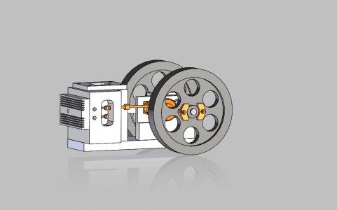
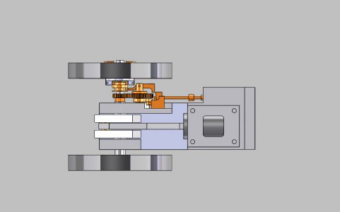
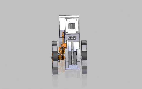
After the success I had with the white gas in the other hit miss engine I built I have decided to build a flat head hit miss engine similar to the one that Ray built a while ago. I looked thru the different hit miss engine builds that Ray did and I liked the flat head design. The valves are not sticking out the top of the head and you do not need a rocker arm and rocker arm mount for the exhaust valve. Below are the design specifications.

1" bore
1.5" throw
Ball Bearings to support the crank shaft
6:1 compression ratio
6" diameter flywheels
David Kerzel style governor (like I used for my previous motor)

Unlike Ray I need to do the design and drawings first then start machining. Once I get the layout done I will post some photos of the layout. I will be doing the design in SolidWorks that I have for work.

Ray, if you see something in the design specs that you think will cause problems feel free to let me know. I am a novice at the engine design.

Thanks
Roger L
 
Your design specs should work just fine.
When I was working on this design there were two things that gave me some time for concern. The first was that the piston liner is not completely sealed all the way around by the cylinder head gasket.
A photo to show my concern.
IMG_1298.JPG

A large section of the liner is not covered by the head gasket and is subjected to the combustion's high pressure gases. The liner must be sealed not only to stop any water leaks but also the high pressure of combustion. A super good seal at this end of the liner is a must.

The second concern was keeping the compression ratio up in an acceptable range. The piston came up flush with the top of the cylinder liner if I remember correctly so the combustion chamber area is totally in the cylinder head. I started with a depth of cut of 0.200 into the head knowing that if that was too deep and the ratio was too low I could plane some off the head. To check the volume of this cavity I filled it with water and then poured the water into a measuring flask. Then I was able to calculate the compression ratio.

The rest of the build is straight forward and much like the engine you just built.

Have fun

Ray
 
Ray:
Thanks for the tip for the cylinder liner. I will make the top rim a press fir and use some cylindrical locktite to get a good seal. When I did the math for the compression ratio I found that all the area is going to be in the head area. Using water to get the area is a great idea. When I did the calculation SolidWorks was able to give me the area of the cutout in the head and I adjusted the depth to get the proper volume. I need to make sure that i include the thickness of the gasket in the calculation. Thanks for all the good information. I will post pictures when I get the design done.

Roger L
 
Ray:
What pitch gears do you use for your designs. I see you cut your own gears. For my previous engine I used 20 degree pressure angle and 32 DP gears. I am having a hard time finding 32 DP cutters. I can find 24 DP cutters. Are the 24 DP gears too coarse for this type of application. The 32 DP gears are a good fit.

Roger L
 
I use Mod1 or Mod.7 cutters as many of my other projects have required metric teeth. The metric cutters are usually less expensive.
I always buy a complete set not individual cutters with future projects in mind.
Ray
 
I have the design almost done. I do not know how Ray can build an engine with out some kind of assembly drawing. If I tried that I would make a boat anchor or have to make parts over and over again. Attached are some views of the assembly. I need to go back and put in all of the mounting holes for the fasteners. But the design looks good.

Roger L
 

Attachments

  • NEW HIT MISS ENGINE ASSEMBLY 1.JPG
    NEW HIT MISS ENGINE ASSEMBLY 1.JPG
    106.9 KB · Views: 15
  • NEW HIT MISS ENGINE ASSEMBLY 2.JPG
    NEW HIT MISS ENGINE ASSEMBLY 2.JPG
    72.1 KB · Views: 15
  • NEW HIT MISS ENGINE ASSEMBLY 3.JPG
    NEW HIT MISS ENGINE ASSEMBLY 3.JPG
    80.1 KB · Views: 16
Roger looks like you are ready to make some chips.
Good job

With a 1 1/2" stroke you may want to double check for an interference issue at the cylinder liner by the connecting rod.

Ray
 
Ray:
I looked at the rod clearance doing the design. I needed to thin up the connecting rod to make sure it did not hit the cylinder liner. I am close to making chips. I will need to get a big block of aluminum for the engine block, some cast iron for the cylinder, (2) ball bearings, and a set of gear cutters. Going to use the MOD 1 gear cutters. I was going to use the MOD .8 but could not find them.

Roger L
 
I have a question for the cylinder liner. Why does everyone use cast Iron for the cylinder liner? Did anyone use 1020 steel? Because cast iron is porous does it hold oil better? Any info would be great.

Roger L
 
I am definitely not an expert in the field of metallurgy but I have used a steel cylinder without a liner in one of my models. Aluminum piston on a steel cylinder for the Henry Ford engine.
Cast iron has a self lubricating quality, it machines relatively easily, and is fairly stable in dimensions. It is also dirty and expensive so why not try using a steel liner and see how it works.
I don't see a problem.

Ray
 
Back
Top