Finding bottom edge of a disk

Maplehead

Registered
Registered
Joined
Feb 20, 2017
Messages
437
Hi All
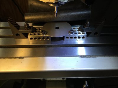
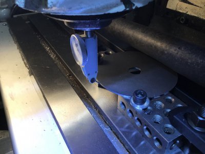
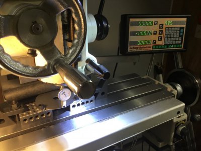
I'm trying to find a quick and accurate way of finding the bottom of a disk that is clamped down on 123 blocks.
The bottom would be that part of the disk closest to the front edge of the mill table. I have some ideas but I'm wondering what you all do.
 

Attachments

  • 986BEBDF-CAC7-45FC-970B-87EB39888827.jpeg
    986BEBDF-CAC7-45FC-970B-87EB39888827.jpeg
    86.3 KB · Views: 58
Find the center, you’ve found your edge. I would use a coaxial indicator, then just move in Y to the edge.
That hole in the middle of the disk isn't perfectly round so if it needs to be for an indicator then I doubt that would be an option.
 
I second what winegrower said

Quick and accurate is an oxymoron

If the center hole is not perfectly round, clamp in a way that you can find center on the outside edge and use the coax.

Easiest and most accurate. But not quickest

There are other ways to skin a cat . Mr Pete has several videos showing other methods


Sent from my iPhone using Tapatalk Pro
 
I think I figured it out, to within an acceptible degree of accuracy, and a quick method.
I put the pictured indicator in the spindle, brought the tip down to the level of the disk, brought the tip in within a few thousands before it touched the disk, zeroed my DRO and then at 1 thousands each I brought in the Y axis and then swept the X axis back and forth. I was looking for needle movement. As soon as the needle moved I played it left to right until I could figure its middle. After that I'll just zero my axis and voila. I'm sure this method got me within a couple thousands of the closest edge.
 

Attachments

  • D40CDC5C-DB86-47FD-8CD6-625B3303CA03.jpeg
    D40CDC5C-DB86-47FD-8CD6-625B3303CA03.jpeg
    106.9 KB · Views: 42
  • 73011062-25BF-4A1C-BAC7-D39DBDE905E1.jpeg
    73011062-25BF-4A1C-BAC7-D39DBDE905E1.jpeg
    114.3 KB · Views: 44
Isn't the bottom of the disc coplanar with the top of the 123 blocks?
 
I think I figured it out, to within an acceptible degree of accuracy, and a quick method.
I put the pictured indicator in the spindle, brought the tip down to the level of the disk, brought the tip in within a few thousands before it touched the disk, zeroed my DRO and then at 1 thousands each I brought in the Y axis and then swept the X axis back and forth. I was looking for needle movement. As soon as the needle moved I played it left to right until I could figure its middle. After that I'll just zero my axis and voila. I'm sure this method got me within a couple thousands of the closest edge.
This method assumes that the plane of rotation of the DTI's probe is the same as that of that extending out from the mill's spindle along the Y axis. Unless the DTI is constructed in that way, there will be significant error.

I would use a pin mounted to the spindle and sweep it along the X axis until the gap between the pin and the edge of disc just stops allowing light to go through at it's narrowest point. The maximum error will be the eccentricity of the pin in TIR divided by two which should be negligible. Sometimes I use this method to locate edges when I don't feel comfortable to let the material rubbed by edge finder.
 
I can't answer your questions as I don't get them but since trying this method I've made three parts and they all come out correctly against the other parts they go with.
 
Here are 3 ways to find the centre of the disk using your edgefinder - none of which require a lot of equipment like a dro or dti.

one move -
two moves -
three moves -

One of these methods may help depending on your setup and equipment.
There are several other 4 move methods on YouTube to try.
 
This method assumes that the plane of rotation of the DTI's probe is the same as that of that extending out from the mill's spindle along the Y axis. Unless the DTI is constructed in that way, there will be significant error.

I would use a pin mounted to the spindle and sweep it along the X axis until the gap between the pin and the edge of disc just stops allowing light to go through at it's narrowest point. The maximum error will be the eccentricity of the pin in TIR divided by two which should be negligible. Sometimes I use this method to locate edges when I don't feel comfortable to let the material rubbed by edge finder.
When using a pin to locate an edge we would spin the pin in the chuck against a dti and mark the high spot with a sharpie. This confirmed that the two concentric spots on the pin were at +/-90 degrees to the mark. Then used either of the two concentric points by having the mark 90 degrees from the face.
 
Back
Top