EzTrak + VFD help

sgisler

Active User
H-M Supporter Gold Member
Joined
Feb 27, 2012
Messages
377
EzTrak + VFD help needed

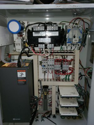
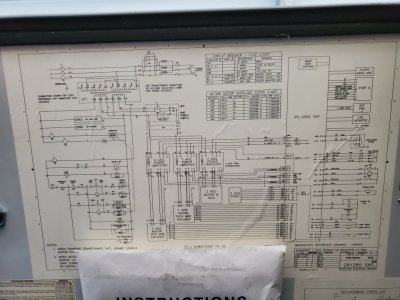
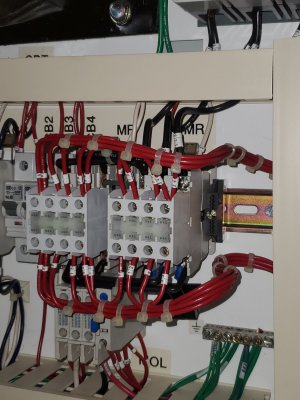
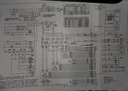
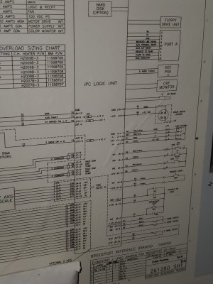
I have a new to me (2000 model) Bridgeport EzTrak 3 axis machine. Existing motor is 230v 3ph. I am running it with a VFD (Teco JNEV-202-H1) 230v 1 ph input. The 230 1ph input goes to the VFD and the EzTrak's internal transformer (which supplies all the low voltage in the enclosure). The 3ph outputs from the VFD go directly to the spindle motor (which means that the original switching relays are necessarily bypassed. So, spindle motor powers up flawlessly, computer powers up flawlessly. I can home the machine and jog all 3 axes with no issue. The problem is that the computer does not know when the spindle is running so it will not run a program. I get a 'start spindle to activate run button' message. My intention is to wire in the operator control console (spindle start, rev/off/fwd and estop) to the low voltage terminals of the VFD, but I don't see how that is going to get the computer to 'see' that the spindle is actually running. I have high hopes that someone here has encountered the same issue on the same machine and can help me understand the next step.
Thanks in advance!
 
Last edited:
Did you ever figure this out? I have exactly the same question:

Like you, I have recently acquired a Bridgeport EZ Trak, also a 2000 model and am in the process of installing a VFD.

I think (hope) I'll be able to figure out how to connect all the switches and etc. from the EZ Trak to the VFD to start the spindle, set motor direction, e-stop, etc.

Have all the manuals and documentation, but so far I have no idea how to program an output on the VFD to connect to the "computer in a box" and tell it when the spindle is running and avoid the "spindle not on" error.

What did you end up doing on your machine?

Anyone else have any experience with this?

Thanks for your help!
 
From sgisler's description, I assume there's an auxiliary contact on the spindle relays that the original control system uses to tell if they are closed (and the spindle is therefore running). Most decent VFDs have a couple of configurable outputs that you can set to activate when the VFD turns the motor on, which could replace the original aux contact. Unfortunately, VFDs are not standardized, so you'll have to read the documentation for your particular VFD to figure out how to do it. If you can post a schematic for the EZ Trak and the model of VFD, someone might be able to give you more specific advice.
 
Hey @hobomachinist,

I've got a Bridgeport with with a factory 2-axis CNC EZ-Trak. I don't recall what year, but it's the original version, model 1.0 or whatever. I thought it was from the 80s or 90s or so --- EDIT: My Bridgeport was born in 1989, so 11 years senior of yours. I doubt you've got the same EZ-Trak version as me. It's got an electrical cabinet on the back with all the CNC goodies tucked away inside.

1649077114441.png

I use a VFD to run mine, and I didn't do anything fancy to do so. I wired mine up about 3 years ago; if memory serves, virtually all the electricals in my cabinet are left intact.

All I do for mine is use the VFD to get the 3rd leg of power; I don't use it for any of the fancy frequency controls or anything like that.

The following is a rough description of how it's wired. I believe I sketched out a diagram while I was doing it, so perhaps I can dig that up if you're interested. This is from memory, so some of the details may be a bit off:
-- 220V single-phase from a 30A breaker in my panel (30A is overkill but I'm also using that breaker for a mini-split AC system)
-- There's a big 'cachunk' breaker switch on the back of the cabinet that controls 3 breakers in the cabinet. I fed the two legs of my 220V input power through two of those breakers and left the third empty.
-- I spliced in my VFD right after the breaker switch. The switch used to have all three phases in/out, so I feed the VFD with my 220V supply and send the 3-phase output straight into the rest of the EZ-Trak control system.
-- The VFD automatically powers on when the 'cachunk' switch is flipped, and I use the regular Bridgeport controls for spindle speed and direction without any inputs to the VFD. It's only purpose in my setup is to get the 3rd leg of power.


This is the VFD I use; I've got a 1.5HP variable-speed J head:


The VFD is tucked away in the electrical cabinet and I've literally not even looked at it since I wired it up 3-ish years ago.

Let me know if you've got additional questions or want me to dig out my schematic.
 
Last edited:
Thanks for all the advice everybody, and sorry for my slow response.

JRaut -- Your solution sounds way, way more straight forward than anything I've been contemplating. Until now and without exception everyone I've talked to has unequivocally told me to never ever put anything between the VFD and the motor.

Whenever I'd start to say "Okay, but what if--"
NEVER. <very stern glare>

But if it's been working fine for you for multiple years, then

Couple questions:

Edit: Sorry, just realized i missed the link you posted to your vfd.
If I understand you correctly, you're using all of the original controls on the mill--start switch, high/low gear switch, emergency stop, etc.-- and each of them are 100% fully functional. Do I have that right?

I have a Fuji FRN0010C2S-7U. Its documentation is pretty clear that putting all those switches and such between the vfd and the motor can and likely would damage the VFD and/or the motor and/or the components wired between them.

bukwirm -- That all sounds correct. The Fuji VFD has a bunch of different user configurable analog and digital outputs and inputs. If someone could tell me how the EZ Trak controller monitors the spindle's status, I could probably configure and connect an output from the VFD to whatever input the controller uses for that.

According to the support techs at EMI (the company that's taken over supporting the Ez Trak from Bridgeport, or Hardinge or whoever), the computer only knows if the spindle is on or off--not speed, direction of rotation, current draw, or anything else.

Here's a copy of the schematic and a pic of what's in the cabinet. Might the component labeled "MOL" may be the auxiliary relay you mentioned?

Thoughts anyone?

And thanks again for everyone's help. You guys are the best.
 

Attachments

  • 20220408_133209.jpg
    20220408_133209.jpg
    86.9 KB · Views: 9
  • 20220408_133130.jpg
    20220408_133130.jpg
    135.9 KB · Views: 9
Last edited:
Hey @hobomachinist,

I've got a Bridgeport with with a factory 2-axis CNC EZ-Trak. I don't recall what year, but it's the original version, model 1.0 or whatever. I thought it was from the 80s or 90s or so --- EDIT: My Bridgeport was born in 1989, so 11 years senior of yours. I doubt you've got the same EZ-Trak version as me. It's got an electrical cabinet on the back with all the CNC goodies tucked away inside.

View attachment 402994

I use a VFD to run mine, and I didn't do anything fancy to do so. I wired mine up about 3 years ago; if memory serves, virtually all the electricals in my cabinet are left intact.

All I do for mine is use the VFD to get the 3rd leg of power; I don't use it for any of the fancy frequency controls or anything like that.

The following is a rough description of how it's wired. I believe I sketched out a diagram while I was doing it, so perhaps I can dig that up if you're interested. This is from memory, so some of the details may be a bit off:
-- 220V single-phase from a 30A breaker in my panel (30A is overkill but I'm also using that breaker for a mini-split AC system)
-- There's a big 'cachunk' breaker switch on the back of the cabinet that controls 3 breakers in the cabinet. I fed the two legs of my 220V input power through two of those breakers and left the third empty.
-- I spliced in my VFD right after the breaker switch. The switch used to have all three phases in/out, so I feed the VFD with my 220V supply and send the 3-phase output straight into the rest of the EZ-Trak control system.
-- The VFD automatically powers on when the 'cachunk' switch is flipped, and I use the regular Bridgeport controls for spindle speed and direction without any inputs to the VFD. It's only purpose in my setup is to get the 3rd leg of power.


This is the VFD I use; I've got a 1.5HP variable-speed J head:


The VFD is tucked away in the electrical cabinet and I've literally not even looked at it since I wired it up 3-ish years ago.

Let me know if you've got additional questions or want me to dig out my schematic.
Just realized you already answered most of my follow-up questions in your original reply. Sorry, about that.
Yes, I would love to see a schematic of your current setup. Or even just a picture of how you wired in your vfd.
 
I’m out of town for the weekend and will try to answer your questions and dig up my schematic when I get back. Please remind me if I forget.

But to answer your first question — yes, all of the original Bridgeport controls are intact and fully functional, and those are all I use. I don’t touch or interact with the VFD in any way.
 
The MOL is a motor overload. The contractor is probably the component immediately to the left of that - image isn't coming through very well, but it looks like it is labeled MR/MF. There should be some more contacts somewhere in the schematic labeled MR/MF (possibly connected the the green SPINDLE RUN light, for example), but I can't read the image well enough to find them all.

I think the forum downscales images, you might be able to post the schematic on Google drive or something so we can get a better look.

Personally, I would probably replace the contractor with the VFD. It looks like the rest of the electronics are powered off the first two phases, so you could drop the third phase entirely. If you post a clearer diagram, I can mark it up enough to get you started. Reviewing the FWD/REV logic and the E20 function code in your VFD's manual might help, as well.
 
Apologies, I know my response time is glacial. Nonetheless, thank you thank you thank you for all your help. Your input has helped me with my thinking a great deal. (At least, I think so. My kids remain unimpressed.)

Attached are some better quality (hopefully) images. Originals for these along with the first round of pics are also available here:


Thoughts?
 

Attachments

  • 20220619_191114.jpg
    20220619_191114.jpg
    243.6 KB · Views: 6
  • 20220619_191316.jpg
    20220619_191316.jpg
    529.1 KB · Views: 8
  • 20220619_191203.jpg
    20220619_191203.jpg
    267.1 KB · Views: 7
VFD's for the most part are not made to run electronic systems so to use it as a power source in this application could cause issues with the electronics and has the potential for a VFD failure. The recommended approach would be to direct connect the motor to the VFD output and disconnect the high voltage (black wires to the MR/MF contactors). Power coming in from the switch L1/L2 would go to the transformer and the VFD input (assuming it is a single phase input). You could also add some CC or J class fusing to the VFD input power. Most likely you would want to leave MR and MF contactors as the switch blocks on top interface with the rest of the control system buttons. You could then use a contact set like L1/T1 of each contactor to operate the low voltage control input on the VFD for the forward (MF) and reverse (MR). The downside of this is that the contacors have been exposed to high voltage/current which cause arching of the contacts and they may not effectively control a low level input that the VFD uses which is typically 24VDC at a few mA. Alternative is to get an additional pair of 120 VAC relays and parallel their respective coil with that of the respective contactor, use the relay to then control the VFD low level inputs. Very simple to just connect the A1 and A2 terminals, and leave all the contactor high voltage wiring (just do not connect to the motor. You have room on the end of the DIN rail for two small 2P relays.

The method above keeps all the stock control functions and is very similar to what I do for what I call a basic VFD install that I have outlined in other threads. I just helped another person program his Lapond VFD for his mill, they are quite basic, in particular in this application where you would be using 2 wire control for the F/R and keep everything intact.

If you want a plug and play option then people would most likely us either a static or RPC and the wild leg is connected to L3 which only is used to operate the spindle motor.
 
Back
Top