- Joined
- Nov 23, 2014
- Messages
- 2,609
Back with another reproduction Erector set part string. This one is part number "HF"; Butt End Plate. The part was introduced in 1929 and was included in a few of the larger sets until 1937. Just a quick “history” lesson. . .
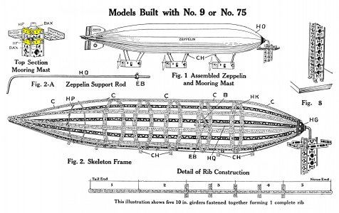
The Graf Zeppelin made an around-the-world trip in 1929. The public was enamored with the 860-foot long airship. The A.C. Gilbert Company sought to capitalize on this fervor by making an Erector set featuring a model of the Zeppelin. Gilbert’s Zeppelin model was 5 feet long and came with parts to make a mooring mast for displaying the model. The model hung from a ¼” diameter steel rod that slipped into the Zeppelin’s nose cone and the top of the mooring tower. The tower had a pair of bushings that screwed to a pair of “HF” butt end plates.
Gilbert's Erector set Zeppelin model from 1929-32
As an aside, Gilbert introduced a 4-foot-long model of a Hudson Locomotive in 1931. This model used one of the “HF” butt end plates in the front truck.
I typically punch steel metal for these parts instead of drilling. Drilling sheet metal with a twist drill frequently leaves a burr. I made an exception for this part as it has twenty no. 19 holes and one 5/8” diameter hole.
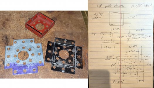
First step was making a drawing. I took an original part, flattened it out and dimensioned the part. The part is not symmetrical on all four side; opposite sides are symmetrical, but the adjacent sides are not. Once I had a drawing, I started with a holding fixture for the Tormach CNC mill.
Here's a sketch made from the flattened out original part (black), an original red part and a prototype blank
My plan was to cut a strip of 18-gauge sheet metal to height, set it in the holding fixture, run the routine to drill the No. 19 holes, then slide the blank in the fixture to do the next part. The holding fixture base was made from aluminum plate. It has a couple of dowel pins at the top that act as a fence to locate the top edge. The blank is clamped in place with a plate of aluminum and two shoulder bolts. The clamping plate was machined to the width of the final blank. Plan was to set the blank in place, force it up against the two pins to set an edge, adjust it side to side until the LH edge was in line with the clamping block, then tighten the two shoulder bolts. The RH edge of the part (which is also the LH edge of the next part) was set by scribing the blank at the RH edge of the clamping block.
I could have used an end mill to knock in the 5/8” diameter center hole, but went with a different approach. Instead, the clamping block has a ¼” hole that is used with a transfer punch to mark the hole. The finished 5/8” hole is popped in with a Roper Whitney punch press. I figured this would be quicker than milling a circle with an end mill. It’s just one pull of a handle to knock in the hole with the punch press. My original intent was to leave the transfer punch in place during the CNC drilling. I made a couple of custom low-profile punches to set in the fixture. I went low profile to avoid hitting the punch with tool moves. In retrospect, it was unnecessary as I removed the transfer punch after marking the center hole.
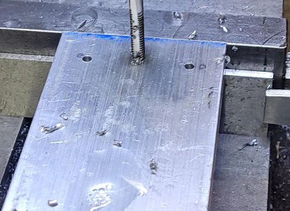
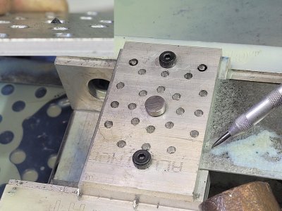
Base plate for the CNC holding fixture. The tapped hole is for a shoulder bolt for securing a top clamping plate. Two adjacent holes are for 1/8" dowel pins that act like a fence for the sheet metal blank.
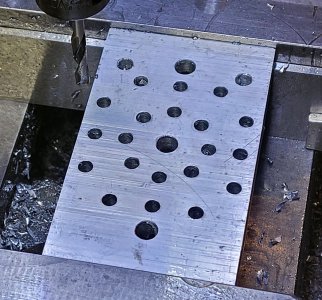
Top clamp plate. Yeah, a lot of holes to drill! The plate was cut to the width of a single part.
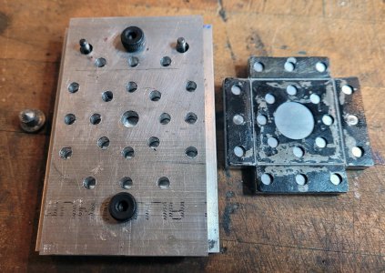
Ready to head to the mill.
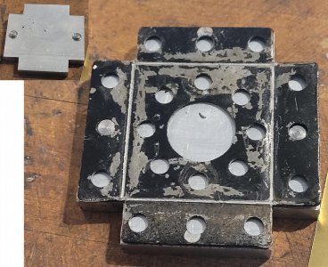
I didn't show it, but also made a check fixture that's the finished size of the blank. My original plan was to set a square blank to the fixture, scribe the corners, then cut them out with a corner notcher.
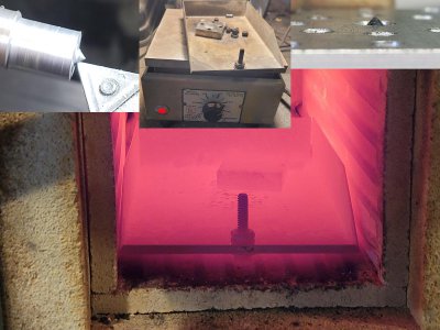
I made a low-profile transfer punch for the center hole. Also a number of locating pins and a bending block. Hardened in a Thermolyne Muffle furnace and tempered on a hot plate.
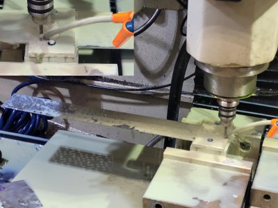
The CNC routine worked really well! It drilled the 20 No. 19 holes into the blank in about 90 seconds. I ran strips of 8 blanks which after drilling and punching were cut into individuals on the Tennsmith shear.
Process was to set the sheet metal blank (cut to height on a Tennsmith shear) under the top clamp plate. Jam it up against the top fence pins, slide to the left until the edge of the blank is flush with the edge of the clamp block, then tighten the two shoulder bolts. Then transfer punch the center hole (to be hand punched later). Scribe the RH edge of the part (which is also the LH edge of the next part). Hit "START" on the CNC control and wait 90 seconds.
Punched the center 5/8" on a Roper Whitney press. I could have done it with the CNC and an end mill, but this was actually quite a bit quicker.
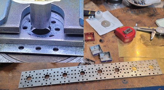
Next was knocking in the corner notches. I did that with a 4-ton corner notcher. I’d made an aluminum template to the size of the blank with a couple of No. 19 pins to locate a blank. Originally, I planned on setting a blank on the fixture, scribe the corners, then cut them. Instead, I set up the work stops on the corner notcher using the aluminum fixture to set the stops. As I mentioned before, the part is not symmetrical. Notching was done by setting the top to the right, cut a corner, then flip the part over for the opposite corner. Then flip it end over end and repeat.
Cutting the corners of the blank
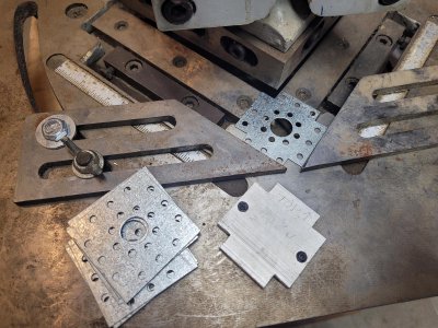
As an aside, the notches aren’t super-critical. However, if they are too shallow, it can cause a problem with the flange bending operation. When/if I make another batch, I’m going to try doing the work on the Bridgeport. My plan would be to run a couple of 5/32” rods through a stack of them to align them to each other. Set the stack in the mill vise using the rods to set the height. I’d edge find the side of one of the 5/32” rods to set X. Bring an end mill down to the rod to set Z. Set a work stop on the opposite rod for flipping the stack to do the opposite side. Also, make a couple of clamp plates from aluminum with 1” hole spacing and screw those to the top of the stack. This would keep the stack from splaying open like a deck of cards when cutting the notch. Lastly, cut the notch with an end mill. Once a corner is done, loosen the vise jaws, remove the stack, turn it 180 and repeat. Then flip the whole stack over and repeat on the opposite side. Would it be quicker than the corner notcher? Won’t know until I try.
Lastly (other than painting) was bending the flanges. The problem I had with my DiAcro brake is the relief at the back of the finger wasn’t deep enough to clear an already bent flange. Imagine a shoe box lid with the inside facing up. The bending finger sets on the surface, the brake bends up an edge. Problem is doing the 3rd and 4th bends as the finger would crush the opposite side flange.
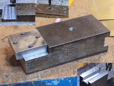
I ended up cutting a block of O-1 tool steel and put in four No. 20 pins (little loose to the No. 19 holes) to locate the blank. The O-1 block was cut to the inside dimensions of the part. I made a custom finger for the brake that clamps down on this block.
As an aside, I made the O-1 block first and tried clamping it down on the brake with a stock finger. Problem was, the fingers move on an arc and set a little higher at the bending point than at the back of the finger. When I tried this method, the O-1 block was about 0.015” from being flat on the table. When I folded the flange, the block lifted some because of the gap. The end result was the face of the part was a little “dished”. That's because the DiAcro brake is rated for something like a max of 1/8" thick material. The flanges are about 0.40".
So, took some measurements of a stock finger and made one out of some mystery steel (I suspect 1040, it was a bit hard to machine). I put in provisions for installing a magnet to hold the O-1 block in place. Full disclosure is it was a total fail. . . I positioned a blank in the O-1 bending block, and set it under the custom finger. For some reason, once I did this the blank fell off the O-1 block. The magnet was pushed out; bending went much better. It might have worked better to put a magnet in the O-1 block also; maybe if I ever need to make another one.
Piece of O-1 tool steel machined to the inside dimension of the finished part. Also drilled and reamed holes for pins that would pick up holes in the blank for locating. Plan was to set the blank on this block, and bend the four flanges on the edge of this hardened block. That ensured the inside size was perfect and that the bends were all in the correct position relative to the holes.
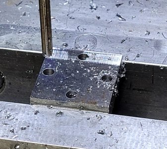
Made a block/finger for the DiAcro brake. I tried bending the flanges using a stock finger to hold the block and blank down, but they were too thick to work correctly. So, made a finger from mystery steel with a rabbeted out area for the hardened steel block.
Bending process was to set a blank on the block, set the block under the brake finger, throw the clamp lever and lift the bending table. Unclamp, rotate 180 and repeat. Then, rotate 90 and do the last two sides.
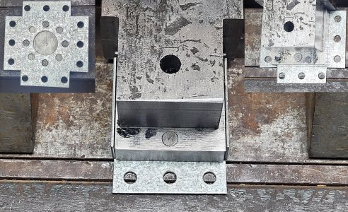
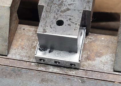
Last bend
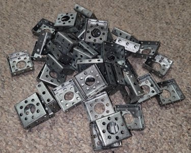
Couple of hours work in the shop
And after painting
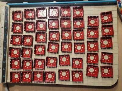
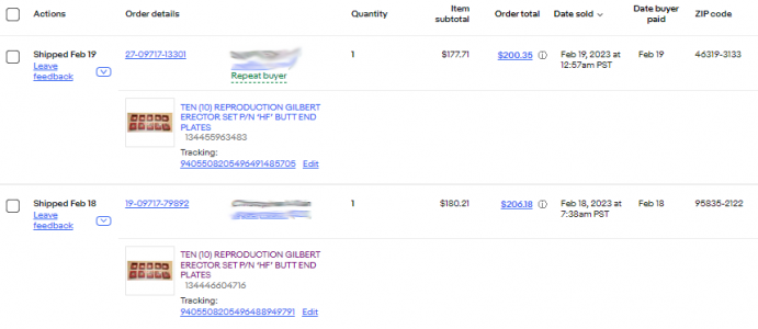
Wish me luck on eBay! There was a guy who used to make these and sold all he could make for $10 each. I can comfortably make around 20/hour, so have a little wiggle room on price.
Thanks for looking, Bruce
The Graf Zeppelin made an around-the-world trip in 1929. The public was enamored with the 860-foot long airship. The A.C. Gilbert Company sought to capitalize on this fervor by making an Erector set featuring a model of the Zeppelin. Gilbert’s Zeppelin model was 5 feet long and came with parts to make a mooring mast for displaying the model. The model hung from a ¼” diameter steel rod that slipped into the Zeppelin’s nose cone and the top of the mooring tower. The tower had a pair of bushings that screwed to a pair of “HF” butt end plates.
Gilbert's Erector set Zeppelin model from 1929-32

As an aside, Gilbert introduced a 4-foot-long model of a Hudson Locomotive in 1931. This model used one of the “HF” butt end plates in the front truck.
I typically punch steel metal for these parts instead of drilling. Drilling sheet metal with a twist drill frequently leaves a burr. I made an exception for this part as it has twenty no. 19 holes and one 5/8” diameter hole.
First step was making a drawing. I took an original part, flattened it out and dimensioned the part. The part is not symmetrical on all four side; opposite sides are symmetrical, but the adjacent sides are not. Once I had a drawing, I started with a holding fixture for the Tormach CNC mill.
Here's a sketch made from the flattened out original part (black), an original red part and a prototype blank

My plan was to cut a strip of 18-gauge sheet metal to height, set it in the holding fixture, run the routine to drill the No. 19 holes, then slide the blank in the fixture to do the next part. The holding fixture base was made from aluminum plate. It has a couple of dowel pins at the top that act as a fence to locate the top edge. The blank is clamped in place with a plate of aluminum and two shoulder bolts. The clamping plate was machined to the width of the final blank. Plan was to set the blank in place, force it up against the two pins to set an edge, adjust it side to side until the LH edge was in line with the clamping block, then tighten the two shoulder bolts. The RH edge of the part (which is also the LH edge of the next part) was set by scribing the blank at the RH edge of the clamping block.
I could have used an end mill to knock in the 5/8” diameter center hole, but went with a different approach. Instead, the clamping block has a ¼” hole that is used with a transfer punch to mark the hole. The finished 5/8” hole is popped in with a Roper Whitney punch press. I figured this would be quicker than milling a circle with an end mill. It’s just one pull of a handle to knock in the hole with the punch press. My original intent was to leave the transfer punch in place during the CNC drilling. I made a couple of custom low-profile punches to set in the fixture. I went low profile to avoid hitting the punch with tool moves. In retrospect, it was unnecessary as I removed the transfer punch after marking the center hole.
Base plate for the CNC holding fixture. The tapped hole is for a shoulder bolt for securing a top clamping plate. Two adjacent holes are for 1/8" dowel pins that act like a fence for the sheet metal blank.

Top clamp plate. Yeah, a lot of holes to drill! The plate was cut to the width of a single part.

Ready to head to the mill.

I didn't show it, but also made a check fixture that's the finished size of the blank. My original plan was to set a square blank to the fixture, scribe the corners, then cut them out with a corner notcher.

I made a low-profile transfer punch for the center hole. Also a number of locating pins and a bending block. Hardened in a Thermolyne Muffle furnace and tempered on a hot plate.

The CNC routine worked really well! It drilled the 20 No. 19 holes into the blank in about 90 seconds. I ran strips of 8 blanks which after drilling and punching were cut into individuals on the Tennsmith shear.
Process was to set the sheet metal blank (cut to height on a Tennsmith shear) under the top clamp plate. Jam it up against the top fence pins, slide to the left until the edge of the blank is flush with the edge of the clamp block, then tighten the two shoulder bolts. Then transfer punch the center hole (to be hand punched later). Scribe the RH edge of the part (which is also the LH edge of the next part). Hit "START" on the CNC control and wait 90 seconds.


Punched the center 5/8" on a Roper Whitney press. I could have done it with the CNC and an end mill, but this was actually quite a bit quicker.

Next was knocking in the corner notches. I did that with a 4-ton corner notcher. I’d made an aluminum template to the size of the blank with a couple of No. 19 pins to locate a blank. Originally, I planned on setting a blank on the fixture, scribe the corners, then cut them. Instead, I set up the work stops on the corner notcher using the aluminum fixture to set the stops. As I mentioned before, the part is not symmetrical. Notching was done by setting the top to the right, cut a corner, then flip the part over for the opposite corner. Then flip it end over end and repeat.
Cutting the corners of the blank

As an aside, the notches aren’t super-critical. However, if they are too shallow, it can cause a problem with the flange bending operation. When/if I make another batch, I’m going to try doing the work on the Bridgeport. My plan would be to run a couple of 5/32” rods through a stack of them to align them to each other. Set the stack in the mill vise using the rods to set the height. I’d edge find the side of one of the 5/32” rods to set X. Bring an end mill down to the rod to set Z. Set a work stop on the opposite rod for flipping the stack to do the opposite side. Also, make a couple of clamp plates from aluminum with 1” hole spacing and screw those to the top of the stack. This would keep the stack from splaying open like a deck of cards when cutting the notch. Lastly, cut the notch with an end mill. Once a corner is done, loosen the vise jaws, remove the stack, turn it 180 and repeat. Then flip the whole stack over and repeat on the opposite side. Would it be quicker than the corner notcher? Won’t know until I try.
Lastly (other than painting) was bending the flanges. The problem I had with my DiAcro brake is the relief at the back of the finger wasn’t deep enough to clear an already bent flange. Imagine a shoe box lid with the inside facing up. The bending finger sets on the surface, the brake bends up an edge. Problem is doing the 3rd and 4th bends as the finger would crush the opposite side flange.
I ended up cutting a block of O-1 tool steel and put in four No. 20 pins (little loose to the No. 19 holes) to locate the blank. The O-1 block was cut to the inside dimensions of the part. I made a custom finger for the brake that clamps down on this block.
As an aside, I made the O-1 block first and tried clamping it down on the brake with a stock finger. Problem was, the fingers move on an arc and set a little higher at the bending point than at the back of the finger. When I tried this method, the O-1 block was about 0.015” from being flat on the table. When I folded the flange, the block lifted some because of the gap. The end result was the face of the part was a little “dished”. That's because the DiAcro brake is rated for something like a max of 1/8" thick material. The flanges are about 0.40".
So, took some measurements of a stock finger and made one out of some mystery steel (I suspect 1040, it was a bit hard to machine). I put in provisions for installing a magnet to hold the O-1 block in place. Full disclosure is it was a total fail. . . I positioned a blank in the O-1 bending block, and set it under the custom finger. For some reason, once I did this the blank fell off the O-1 block. The magnet was pushed out; bending went much better. It might have worked better to put a magnet in the O-1 block also; maybe if I ever need to make another one.
Piece of O-1 tool steel machined to the inside dimension of the finished part. Also drilled and reamed holes for pins that would pick up holes in the blank for locating. Plan was to set the blank on this block, and bend the four flanges on the edge of this hardened block. That ensured the inside size was perfect and that the bends were all in the correct position relative to the holes.

Made a block/finger for the DiAcro brake. I tried bending the flanges using a stock finger to hold the block and blank down, but they were too thick to work correctly. So, made a finger from mystery steel with a rabbeted out area for the hardened steel block.

Bending process was to set a blank on the block, set the block under the brake finger, throw the clamp lever and lift the bending table. Unclamp, rotate 180 and repeat. Then, rotate 90 and do the last two sides.

Last bend

Couple of hours work in the shop

And after painting

Wish me luck on eBay! There was a guy who used to make these and sold all he could make for $10 each. I can comfortably make around 20/hour, so have a little wiggle room on price.
Thanks for looking, Bruce


