Erector set part number 'BM' Clam Shell bucket build

BGHansen

H-M Supporter - Diamond Member
H-M Lifetime Diamond Member
Joined
Nov 23, 2014
Messages
2,606
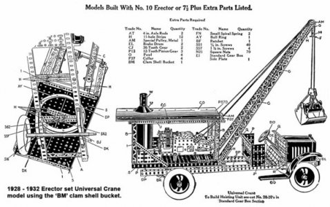
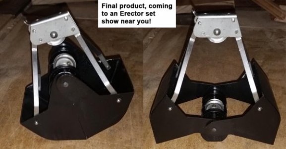
Here’s the build of another reproduction Erector set part. This one is part number ‘BM’, a clamshell bucket. First a quick history lesson. The ‘BM’ clamshell bucket was included in the largest set (No. 10) from 1927 – 1932. The bucket was nickel-plated in 1927 and early 1928, but switched to black-painted in late 1928 - 1932. The part was originally tooled by the Kelmet Corp. for a stiff-leg derrick toy and a pressed steel toy truck. A. C. Gilbert acquired the company in around 1926 and adapted some of the parts into the Erector set line including the ‘BM’ clamshell bucket.

Lots of details on this one; five major components are involved in the build of this part, plus the overall assembly. I’ll break each part up into its own post. The components are: Scoop, ‘AM’ pulleys, top bracket, links and weight.

The ‘BM’ has a weight at the center area that when dropped causes the bucket to open. Lifting up on the weight closes the bucket. There are pulleys on the top bracket and weight that were strung to axles/drums to pull/drop the string to work the bucket.

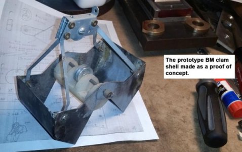
First the construction of the scoop. I acquired a sketch of the ‘BM’ clamshell from a fellow collector and made the pictured prototype for a proof of concept. The original scoops were made from 0.040” steel and were pressed in one shot. That’s beyond my capability, so I went with a folded up, then welded design.

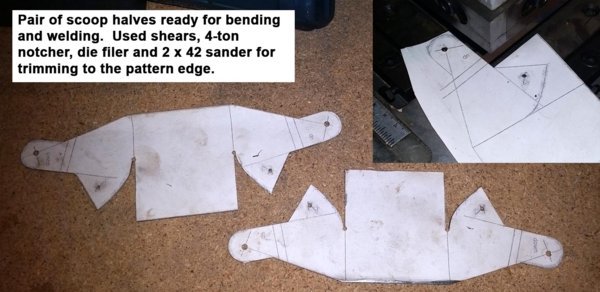
I make up patterns using Adobe Illustrator and Photoshop. These are printed and glued to the sheet metal with spray adhesive. Lots quicker than making a master template that gets scribed to the blank. Trimming of the pattern was done on my Tennsmith shear, 4-ton notcher, 2x42 sander and Oliver die filer.

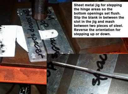
Two scoops are hinged at the center; for the bucket bottoms to come together flush to each other, the overlapped hinge areas need to be offset from each other by ½ the thickness of the blank. One side is pressed up, the other down. This is done on a 12-ton shop press with a sheet metal jig. Slip the hinge area of the scoop through the opening between the spot-welded jig and mash it on the press. The orientation is reversed for either bending the hinge area up or down.

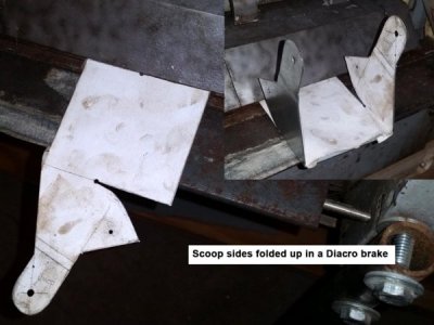
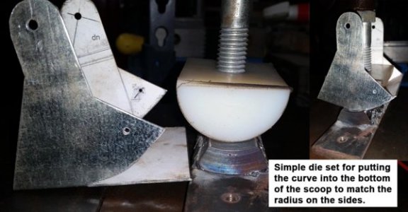
Next it’s to the brake for folding up the sides of the bucket. The bottom of the bucket has a curved area which matches the side profile. Made a die set from Delrin and a piece of tubing for pressing in that profile on the shop press.

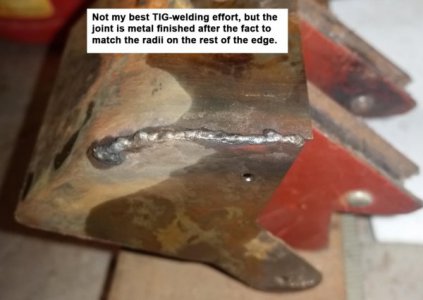
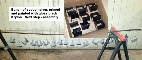
Once formed, the scoops are TIG welded and metal finished. Last step is to prime and paint them. I have a nickel-plating tank from Caswell Plating for making nickel scoops. If you’re interested, hit the web site www.girdersandgears.com and look under restoration projects. There’s a link posted there of me nickel-plating some parts. If I get ambitious, I may try making the scoops out of 304 stainless for the nickel-plated look or just plate some plain steel ones.

Bruce
s1.jpg s2.jpg s3.jpg s4.jpg s5.jpg s6.jpg s7.jpg s8.jpg
 
This posting is for the Erector part number ‘AM’ pulleys. Stainless steel in a No. 2B finish looks very close to nickel plating, so I opt for that material for all of the plated parts. Not the same process that was used at the Gilbert factory, but it saves me the steps involved in plating.

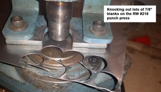
The ‘AM’ pulleys are 7/8” diameter. A Roper Whitney #218 and the appropriate punch/die make short work of the blanks. Then a central 1/8” is punched with a RW #5 hand punch. Stock for this part is 0.018” thick 304 stainless.

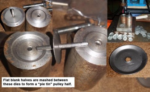
I didn’t show the construction (made the die years ago), but mash the flat blank into a pie tie shape between two pieces of steel on the shop press. There’s a central 1/8” pin to hold the blank centered on the die.

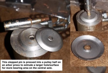
The pulleys have an extrusion at the center to give more contact area when slipped onto an axle. This is done with a pin that starts at 1/8” diameter and steps up to 5/32” (axle diameter). Use the arbor press for this operation.

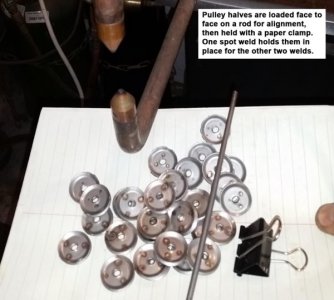
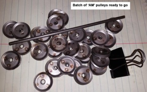
Next is welding two of the pulley halves together. They are aligned with a piece of 5/32” rod and clipped with a paper fastener. A quick hit with my spot welded tacks them together, then two other welds are added.

I’m contemplating making up custom weld tips to make this operation go quicker. I’m thinking about a bottom electrode that’s a ring with an insulated center aligning pin. Just set the two pulley halves in place over the pin for alignment. The top electrode will have three projections for doing the 3 spot welds. Will need to make the top detail on a ball joint so it’ll freely rotate to equalize the pressure on the 3 electrodes. Maybe when I get caught up on other projects . . . In the grand scheme of things, 75 of these pulleys are needed to make up 25 ‘BM’ assemblies which was the size of my last batch made up 10 years ago. Maybe just stick with the manual process . . .

Bruce
p01.jpg p02.jpg p03.jpg p04.jpg p05.jpg
 
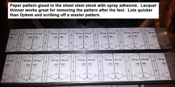
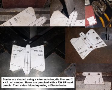
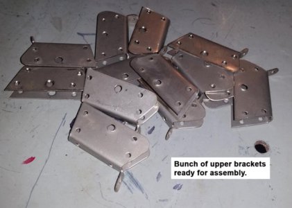
Next part is the upper bracket. These are made from 0.030” thick #2B finish 304 stainless steel. Nothing too Earth-shattering here, glue a paper pattern to the blank and trim to size using a 4-ton notcher, die filer, 2 x 42 sander and a 1 x 30 sander.

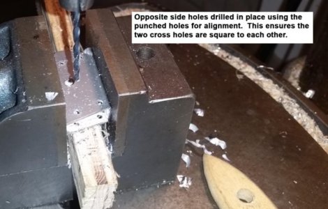
Folding is done on my Diacro brake. The top side holes need to be aligned to each other, so instead of punching both sides in the flat state and hoping they line up after folding, just one side is punched. Then on to the drill press to knock through the opposite side holes.

Another potential future project here. I’m contemplating making a punch/die set that knock all of the holes on one side in one shot. Then fold up the part and use the already punched holes as a guide to knock through the other side holes. Drilling sheet metal always leaves a burr that requires another operation. Punching leaves a nice clean hole. Again, maybe something when I get a spare moment . . .

Or maybe invest in a Roper Whitney model XX hand punch which has a deep enough throat depth to knock through the opposite side holes. My #218 press could do the trick also; just trying to avoid set ups which take time.

Bruce
u1.jpg u2.jpg u3.jpg u4.jpg
 
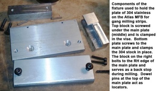
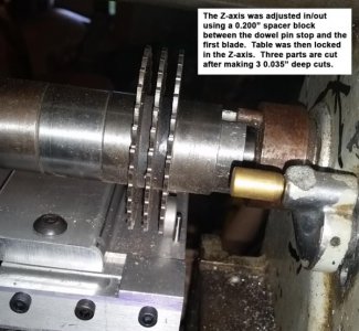
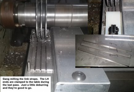
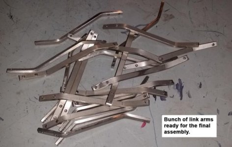
Next parts are the link arms. These are made from 0.10” thick 304 stainless. Too thick for my Tennsmith shear, so these are cut on my Atlas mill with slitting saws. I bought 3 brand new B&S 3” diameter cutters off eBay for this operation. The links are 0.195” wide so made up some arbor spacers a few thousandths over that for gang milling.

I made up an aluminum holding fixture that’s held in the mill vise. The 3 saws let me cut 3 of these links at a time. The fixture as a couple of dowel pins to set the Z-axis of the stainless stock; loosen the clamp screws and slide the stock toward the headstock until it hits the pins, then tighten the clamp screws. There’s a backstop on the right side of the fixture also for support during cutting.

I make about 0.035” depth of cut passes and use plenty of cutting oil. The left ends of the stock are clamped to the fixture on the last pass prior to cutting through on the RH side. My fear was the loose pieces would get wedged in my cutters and break/bend something. After cutting, there’s some quick metal finishing on the edges using 2 x 42 and 1 x 30 belt sanders.

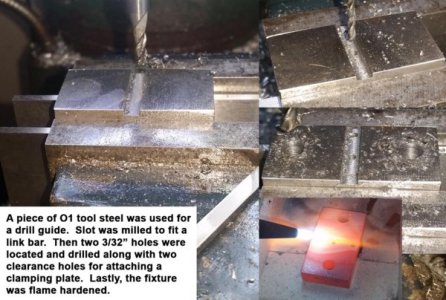
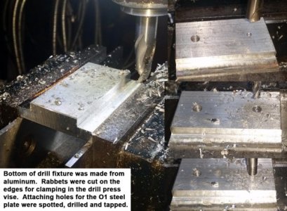
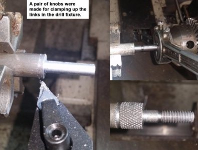
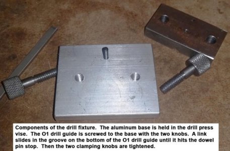
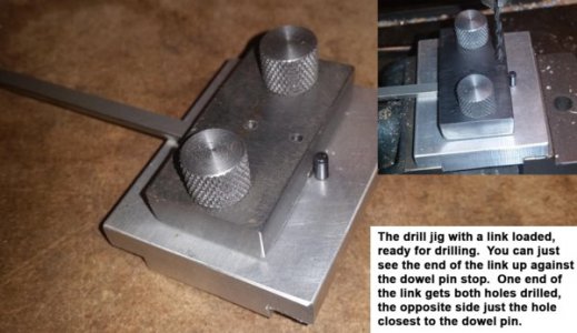
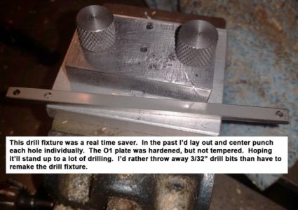
Then onto the attaching holes. The link arms are held to the upper bracket and scoop halves with 3/32” tinner’s rivets. One end gets two holes, other gets one. Hole spacing is critical for alignment to the top bracket, so an O-1 hardened drill fixture was made for this operation. It works really well, loosen the knurled knobs, slide the link in until it bottoms out on a dowel pin (sets position), tighten the knobs and drill away.

Last step is bending the link arms. This is done on a Diacro brake. Kind of critical dimensions required here too. Two links set face to face at the top with the spread of the opposite ends being just shy of the width of a scoop half. I usually go just a little too deep with the bends as it’s easy to squeeze the bends with a pliers after the fact for fine tuning.

Bruce
la1.jpg la2.jpg la3.jpg la4.jpg la5.jpg la6.jpg la7.jpg la8.jpg la9.jpg la10.jpg
 
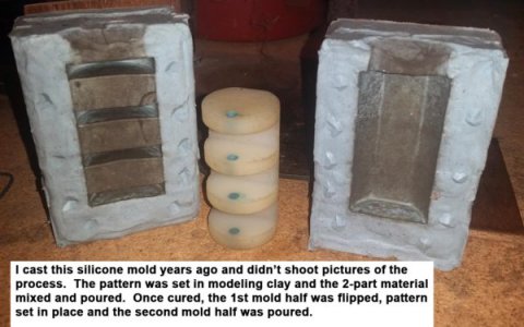
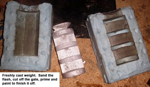
Next part is the central weight. The original ‘BM’ scoops used a cast-iron weight. That’s beyond my capability so went with a silicone mold and lead. I made a pattern from Delrin and cast a mold using a 2-part silicone material from Micro-Mark. I didn’t detail the mold making process as it was made years ago.

I had a good idea on the weight axle hole that has saved a lot of downstream frustration. The weight is about 2 ½” wide and has a hole through it for an axle. I drilled the hole in the Delrin pattern, then filled in the holes with modeling clay. Then touched off on the holes with a drill bit to mark the center. This gives a cast-in center drilled hole making it easy to drill the axle holes from either side and ensure they’re aligned.

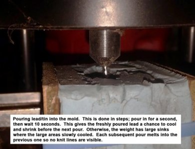
Use a Lyman pot for melting the tin/lead mix. Hold the mold halves together with rubber bands and pour in the lead a little bit at a time. The weight is about 1 ¼” diameter and has a tremendous amount of thermal mass. The upper ribs sink like crazy if it’s poured in one quick shot. Nice thing about casting lead is the interrupted pouring in the mold doesn’t show up in the final part. Kind of like welding a nice stack of dimes, taking a break, then continuing the weld.

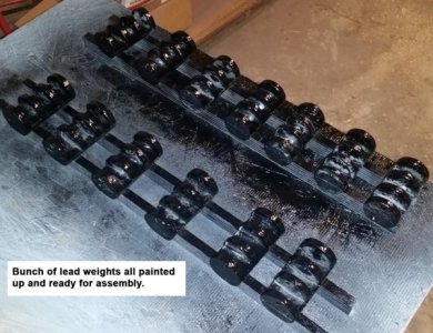
Any flash on the weights is sanded off, then drilled, primed and painted black. There’s a metallurgical phenomenon that I will never understand . . . Lead melts at 622 F, Tin melts at 450 F. But if you mix them at a ratio of 2/3 tin to 1/3 lead the combo melts at about 360 F (eutectic point). Point being, the silicon mold material is good to a temp of around 625 F, so I mix in a fair amount of tin to keep from smoking the mold.

Bruce
w1.jpg w2.jpg w3.jpg w4.jpg
 
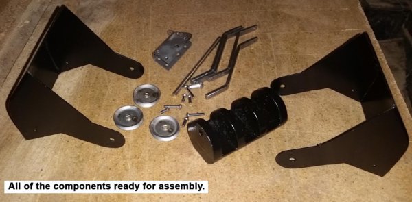
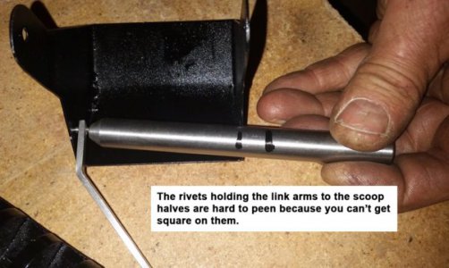
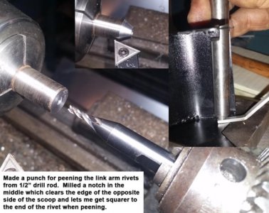
On to the final assembly . . . The ‘BM’ components are held together with tinner’s rivets. I use stainless steel ones here which look very close to nickel plating. The troublesome ones are the 3/32” rivets that tie the link arms to the scoop halves. Don’t get a straight shot on these, so I made a punch of sorts from ½” drill rod with an area notched out to clear the opposite side of the scoop. I’m still not on perfectly square, but it works pretty well.

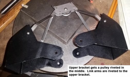
The upper bracket gets an ‘AM’ pulley riveted in place. Then the link arms are riveted to the upper bracket. One set of link arms get two rivets so they are fixed solidly to the upper bracket. The other two link arms get just one rivet and pivot about the upper bracket.

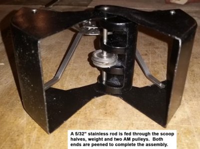
Lastly, a length of 5/32” 304 stainless rod is fed through the scoop halves, weight and 2 ‘AM’ pulleys. Both ends are peened to complete the assembly.

So there it is in all its glory, the Erector set ‘BM’ clamshell bucket available at an Erector set show in your neighborhood!

Bruce
fa1.jpg fa2.jpg fa3.jpg fa4.jpg fa5.jpg fa6.jpg
 
Hi Bruce,

Do you have a bending jig for the link arms to get them all identical?

The time spent with the great write-up and labelled photos is greatly appreciated.
Thanks for sharing this!

-brino
 
Hi Bruce,

Do you have a bending jig for the link arms to get them all identical?

The time spent with the great write-up and labelled photos is greatly appreciated.
Thanks for sharing this!

-brino
Hi Brino,

Glad you like the write up! On the plus side, it gives me a place to look up how I make them if I need to make up another batch in 5 or 10 years. I never used to make up work instructions for all of these parts but am now! My memory isn't what it used to be.
I bend the links in a Diacro universal brake, adjust the stop screw to get the angle correct. I have a gauge made up with the correct offset for a quick check. I usually set 4 of them side by side in the brake and bend the lot at the same time. Actually the angle isn't as important as the offset from the ends. The gauge nets off one end of the link and has a reference line for the opposite end. Kind of like a height gauge check with one of the drilled surfaces set flat to the table. The critical dimension is the width of two links when set face to face; they need to fit inside of the scoop halves. That's why I usually bend them just a little long as I've found it easier to squeeze the bend with a pliers to lessen the offset than to try to add more bend. I'm probably too anal about the whole splitting hairs thing . . .

Best regards, Bruce
 
Back
Top