Engineering anomalies

Dranreb

Active User
Registered
Joined
Sep 20, 2012
Messages
560
Engineering anomalies...need enlightenment please explain.

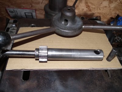
Pondering on how two gear teeth became broken on this shaft, it seemed to me that there was a strange miss-match between the two pins involved.

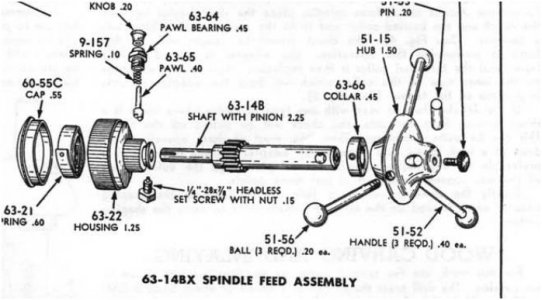
On one end the quill feed handle is held on by a huge pin, but the gear is held on by a relatively tiny taper pin which is obviously up to the job as it hasn't failed under obvious abuse.

So my question is what is the point of the huge pin the other end, is this just to look butch and strong to impress buyers, or is it a necessity?
DSCF9392.JPG

All a bit strange to me...suggestions welcome..

More anomalies to follow :)

Bernard

DSCF9392.JPG
 
Are you sure the gear and the sleeve are the same part? My guess is they are seperate pieces and just look like one.
 
Sorry randy, didn't describe that well did I...the shaft is all one piece with a separate gear against a shoulder on that shaft, hence the taper pin to prevent it rotating.
 
Re: Engineering anomalies...need enlightenment please explain.

Pondering on how two gear teeth became broken on this shaft, it seemed to me that there was a strange miss-match between the two pins involved.

On one end the quill feed handle is held on by a huge pin, but the gear is held on by a relatively tiny taper pin which is obviously up to the job as it hasn't failed under obvious abuse.

So my question is what is the point of the huge pin the other end, is this just to look butch and strong to impress buyers, or is it a necessity?


All a bit strange to me...suggestions welcome..

More anomalies to follow :)

Bernard

My uninformed guess: the gear-shaft-handwheel assembly was designed by committee. Or the one you have is an update of an earlier design. Perhaps the original had the gear+shaft as a single part, joined to a handwheel via a rather large pin. Then some bright intern came along and said, "Hey, we can save $0.15 by machining the gear as a sleeve and this little pin will me more than strong enough to keep it from spinning on the shaft."

Walt
 
My guess is that the gear was originally made on the shaft and was damaged. Someone machined off the original gear and pinned on a new one. The large pin may also not be original.
 
The small pin holding the gear is actually taking less load if I understand correctly, because the shear faces are on a smaller diameter... though not enough to explain the large difference.

I suspect the gear pin is sized to be strong enough, while the larger pin on the handwheel is also intended to take abuse, odd direction loading when people push and pull on it, and for it to survive repeated removal and reinstallation.

Or the manufacturer just had a bunch of handwheels with big holes in stock...
 
My uninformed guess: the gear-shaft-handwheel assembly was designed by committee. Or the one you have is an update of an earlier design. Perhaps the original had the gear+shaft as a single part, joined to a handwheel via a rather large pin. Then some bright intern came along and said, "Hey, we can save $0.15 by machining the gear as a sleeve and this little pin will me more than strong enough to keep it from spinning on the shaft."

Walt


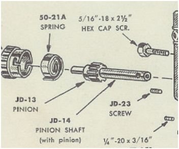
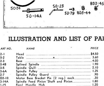
Great theory Walt, and one that had passed though my brain also, but I've had a look at a few parts lists and it seems the gear was always a separate part, but sold already pinned to the shaft, although some ambiguity exists....I did find an early hand drawn parts list with the taper pin clearly marked but couldn't copy it. We are talking Atlas here, who were not well known for wasting ink paper or metal!:LOL:


My guess is that the gear was originally made on the shaft and was damaged. Someone machined off the original gear and pinned on a new one. The large pin may also not be original.

Makes sense OM considering this machine has had a hard life, but the separate gear and large pin are definitely original spec.

shaft gear 2.JPG

shaft gear 1.JPG

shaftgear 3.JPG


The small pin holding the gear is actually taking less load if I understand correctly, because the shear faces are on a smaller diameter... though not enough to explain the large difference.

I suspect the gear pin is sized to be strong enough, while the larger pin on the handwheel is also intended to take abuse, odd direction loading when people push and pull on it, and for it to survive repeated removal and reinstallation.

Or the manufacturer just had a bunch of handwheels with big holes in stock...

That's most likely as near enough as makes no odds FM, maybe someone has the calcs for these things handy?

I had thought maybe the small pin was originally a shear pin, which would save the gear, but then there would be spares listed and they're not...

Thanks for the input chaps, not sure why this has become an obsession, this forum has done this to me, is there an antidote? :biggrin:

Bernard

shaft gear 1.JPG shaft gear 2.JPG shaftgear 3.JPG
 
Engineering people over engineer gizmos all the time. The manufacturing dept is told to make the gizmo for as cheap as possible. One way is not re-inventing the wheel. One way to do so is to use what is at hand and save money for the bean counters.
Likely used a handle from another machine or old stock patterns.
Pierre
 
The loads on the two pins are very different. They are both resisting the torque applied to a lever but the levers are different lengths. The lever length at the pinion end is from the shaft center to the center of pressure on the pinion teeth. Looks to be about 3/4" or less. The lever length on the handle end is from the center of the shaft to the center of the ball ends. Looks to be eight or ten inches. So the load difference on the two pins is directly proportional to the length difference of the two levers. I'm guessing the ratio is about ten to one.
 
The loads on the two pins are very different. They are both resisting the torque applied to a lever but the levers are different lengths. The lever length at the pinion end is from the shaft center to the center of pressure on the pinion teeth. Looks to be about 3/4" or less. The lever length on the handle end is from the center of the shaft to the center of the ball ends. Looks to be eight or ten inches. So the load difference on the two pins is directly proportional to the length difference of the two levers. I'm guessing the ratio is about ten to one.

Actually, no. The loads are only slightly different, according to the shaft diameter, since you can't put any more torque on the shaft via the handwheel than the pinion can react (plus the torque from the return spring, which is minor by comparison).
 
Back
Top