ENCO 110-2079

Matt123

Registered
Registered
Joined
Jul 19, 2020
Messages
2
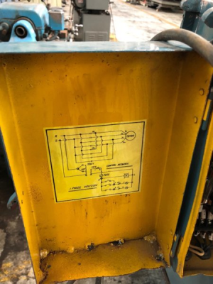
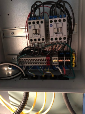
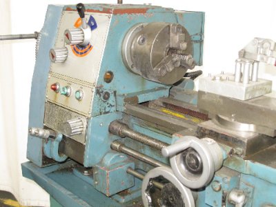
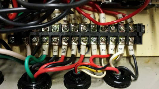
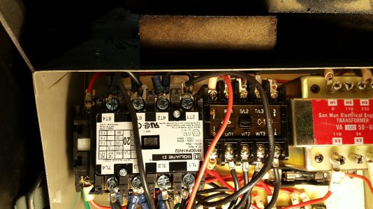
I recently purchased this lathe and the guy i bought it from dropped it and it totally destroyed the electrical cabinet- i have purchased new contacters transformer, and over-load breaker- i was given a electrical schematic for a Grizzly lathe that is similar but is not the same at all- if i manually engage the contactors i can get the lathe to turn on but all of the wiring off the switches is completely different than the grizzly. My question is does anyone have a maintenance manual, a good schematic for this machine or could take a clear picture of the cabinet on their machine. Any help is greatly appreciated!

thank you!

Matt
 
I have an Enco 110-2033 (12x36). It probably had the same electrical layout you had. Mine was in rough shape and I opted to replace it entirely.

Here is the original electrical schematic.
1595258054739.png

Here is my updated wiring. I have plans to redo this box since there is no fusing and the operator controls are directly coupled to the AC line.
1595258109190.png

What you need is two 4-pole contactors with usable coil voltages. I opted to power mine with 240V right from the line, but you could add a power supply or control transformer if you prefer.

Ideally the contactors should be mechanically interlocked to prevent any case where they both come on at the same time (shorts directly across the line).

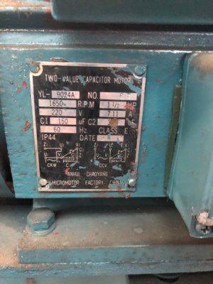
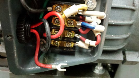
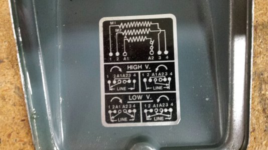
The motor is a 4 wire single phase reversible motor. Your best bet is to look at the motor nameplate for the wiring detail. Here is mine...
Motor Nameplate (1).jpg
 
Hi, here's the manual for the 075 / 079
The schematic is at the back
The diagonal lines that say 1mm2 and 2.5mm2 just indicates wire diameters, not connections
-Mark
 

Attachments

  • Enco-110-2075-79 -Manual-11-13-14.pdf
    3 MB · Views: 18
You are correct. Information on these older Enco lathes is hard to come by. I have a 110-2070 built in 1989. Here are pictures of the lathe and schematics of the wiring I made several years ago. Not sure it applies to your lathe but it's a start.

20110620142145645_L.jpg20161018_125825_resized.jpg20161018_125842_resized.jpg20161215_104309_resized.jpg20161215_104733_resized.jpg
 

Attachments

  • Electric Box Wiring Diagram Revised 12-16-2016.pdf
    374.8 KB · Views: 12
  • Lathe Motor Terminal Box.pdf
    17.1 KB · Views: 13
Back
Top