Emco Compact 8 Headstock Shims?

No offense, @machPete99 , and I know that a whole lot of other guys agree with you but some of us don't trust these MT test bars. There are too many stacking tolerances, the accuracy of the grind and the accuracy of the spindle Morse taper are unknowns and the impact of gravity on that long bar also contributes to uncertainty. In my opinion, the best way to check the headstock position relative to the ways is to make a test cut because it proves itself. Let me explain.

Take a 1 to 2" bar of softer steel, like 12L14, and chuck it up with about 4-6" of it sticking out. Since this is a first operation, the chuck you use doesn't matter. With a well ground, sharp HSS tool, take a skim pass of about 0.010" deep to remove the skin, then take a 0.003" cut to size it and finally take a 0.001-0.002" finish pass down the whole length of the bar. Now measure the OD at both ends and the middle. If there is a difference, move the headstock until repeated 0.001-0.002" test cuts produce zero difference along the entire bar. This is a dynamic test that accounts for the specific peculiarities of the lathe and it proves the headstock position.

There are many ways to align the headstock but this one is simple, repeatable and reliable. Maybe consider it as an option?
 
What Mikey said. Plus saves $ for other things.
 
Any bed twist will have to be leveled out before doing anything else, no?
 
Any bed twist will have to be leveled out before doing anything else, no?

I believe the order is:
  • Make sure the machine is well supported and not wobbly
  • Level the machine with a master level
  • Square the headstock as described above
  • Align the tailstock
 
You definitely want the lathe bed leveled as a first step.

The test cut method is certainly a time honored method and can do what you want. You will need to take a very light cut to avoid deflection, and plan to do a bunch of passes, on any change in setup.

I happen to like using a test bar. You can rotate the bar between centers to check its accuracy. Rotate the spindle + bar and check for runout which will give you an idea of the bar + spindle taper accuracy. If you position it at the median you cancel that out, which is essentially the "Rollies Dad Method", and you could also just chuck up a piece of precision ground stock for it.

The test bar can also be used to check the geometry of the tailstock, assuming they are the same taper. You will need to decide if it is worth the investment.
 
Last edited:
I do appreciate all the guidance. Right now this little machine is sitting on a plank on sawhorses, not even bolted down.

I'll have to either make a small extension wiring harness to get the control box out of the way or temporarily mount the panel a little higher to access the rear head stock nuts to allow a cutting alignment test. I might pony up the bucks for a test bar in order to get it close without being powered up.

The carriage came apart yesterday. I have to clean it and put it back together before I loose any pieces. Sort of driving me crazy that there's a tiny spring clip holding the half nut cam on the shaft. Recessed hole and no "ears" on the spring clip. I can't see how to get it out without breaking something. In the goodies with the lathe, there were brand new carriage gear shafts that I'd like to use, but held together with the same little clip. I think it best to just flush the apron clean and get it back together for now.

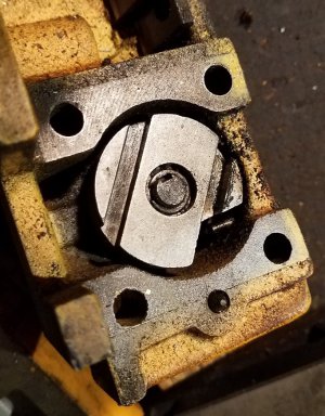
Here's a pic of the clip. There has to be some sort of tool to get in there to get that apart. Haven't checked on-line yet, but if there's a good brand that works well for this tiny stuff, please chime in.

HalfNutCam_SpringClip_cropped_small.jpg

This machine came from a shop in PA that closed. Lots of soft brown powdery material on it. Hopefully Garolite or something harmless. Keeping the gloves on until I get it clean.

TomKro
 
If I recall correctly, I rotated the clip so one end cleared any obstruction, put a screwdriver in that slot on the shaft and just levered the clip a tiny bit and it popped off. It doesn't take a lot of force to get the clip to release.

Insofar as procedures for set up goes, I would mount the bed to a bench or stand where it will be sited. I would assemble the lathe completely next. The headstock will be adequately accurate if you just bolt it to the bed; the V-ways will orient it pretty well. Get the rest of the lathe assembled and do a rough leveling with a machinist's level sitting on the cross slide. Once the lathe is assembled and running, align the headstock with the ways. However you do it, this has to be the first real thing you do because everything else depends on the headstock being in alignment. Once you get the headstock aligned, do a precision leveling of the lathe and finalize it with a 2-collar test. Then align the tailstock with the headstock and you're done.

Setting up a lathe is not rocket science but it has to be done in the right sequence and with great care. You are also going to find that the most accurate way to set up and test your lathe is with test cuts and test bars cut on your specific lathe. This applies to headstock alignment, leveling and tailstock alignment. While there are certainly optional ways to do all these things, I've tried most of them over the years and it is faster and more accurate to use the lathe itself. There is a wealth of detail about all of these things on the net - happy searching.
 
Resurrecting a really old thread.

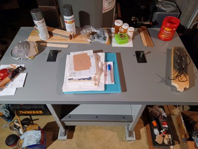
I decided there was way to much "stuff" laying around the basement, so the Emco Compact 8 bench had to be made from available material with a minimum of new hardware purchases. So now I have a wood bench made from mostly scrap lumber and angle iron, leveled with hockey pucks, and bed alignment with hardware intended for another project.

AssembledBench_resized.jpg

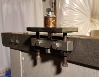
The bed attachment and bed leveling worked out better than expected. I used 7/16 hex screws to tie the bed down, and two 3/8 inch extra fine setscrews on each end pushing upward to allow alignment. The setscrews and tiedown bolts thread into a 3/4 inch square steel bar. I neglected to account for the width of the hex nuts locking the adjusting screws, so I had to pad out the square steel bar with a few washers. The setscrews push up against a flat bar, slightly recessed into the table top.

Here's a close up with no tabletop or lathe in place. The table top sits on the horizontal flange of the angle iron, and the lathe bed is located where the old brass bushing sits. Each end of the table top has a pocket for the flat bar, and 3 through holes for the tie down bolt and two setscrews.

C8_BedJackPad_resized.jpg

I had a test bar on my Christmas list last year, so I was able to use that for preliminary alignment. It should be interesting to see how close it comes compared to a test cut. I've also temporarily mounted the control panel a couple inches high in order to maintain access to the headstock tie down nuts, in case more alignment is required.

Presently, I don't have the banjo properly set up. I'm missing some small spacer washers that allow tightening of the change gear hardware. The washers are located against the banjo bar, close to the T-nuts.

Does anyone possibly have dimensions for those spacers? Are they built with a shoulder to avoid running against the gears, or just configured as a flat washer? Any assistance is greatly appreciated.

TomKro
 
I am eager to see your finished result, so I can use your setup for my workbench.
 
Back
Top