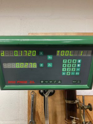
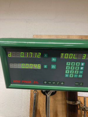
Hi. New to the forum. I have the DRO Pros EL700 installed on my mill - it's the smallest knee that Grizzly sold. I also have a CNC Masters CNC Max mill. Both sport some QC tooling. I've been trying to expand my DRO use beyond the lathe dimensions and milling offsets and center (really love that feature). For the lathe (Grizzly 13x30) I have the 2L DRO and just figured out how to use tool offsets which I think will be very handy.
Anyway, the question: For the EL700 Milling mode - I can create/edit tools. I can select tools (as per the top of the display). However absolutely nothing I enter has any effect on the readout. I would expect a tool change to change the current offset - in this case S (Z + U) or the Z axis tool offset. I can't actually find a use for the tool information at all. The manual only says how to edit/create a tool - which I have done. DRO Pros was unable to help me at all. I've searched the internet for quite some time, pulled up videos... nada. Perhaps it's just not possible. But it seems weird you can create a tool and not actually use it.
I have reasonably accurately measured each tool. I have a Haimer probe that I use. I created a holder for it using the Tormach TTS machinable holder and set it to be very very nearly exactly 5" when zeroed to Z (convenient, not necessary). I was hoping to then use that as the basis for other tooling, for example my 1/2" end mill. I know the difference between the Haimer and the end mill.
I've done tool changes on the CNC mill, that's a different beast altogether with the tool path reflecting the newly selected tool.
Anyway, thanks in advance for any pointers.


