- Joined
- Mar 9, 2018
- Messages
- 468
Episode 30 || Engine Stand
As promised -- two posts in rapid succession.
This post gets me to a point that I’m pretty darn happy with. Quite frankly, if I were to stop here and not even try to fire it up, I could walk away a happy man. But I shall take it through to the end and get it running (I hope).
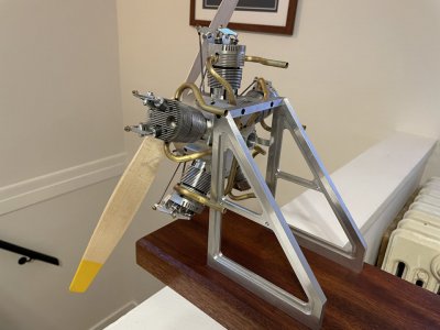
It took me seemingly forever to model up a stand that I liked in Fusion. But here it is. Some of the geometry is complicated because I’m basically translating the 10 facets of the crankcase into the two vertical stand components.
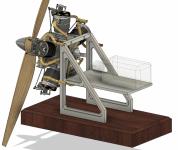
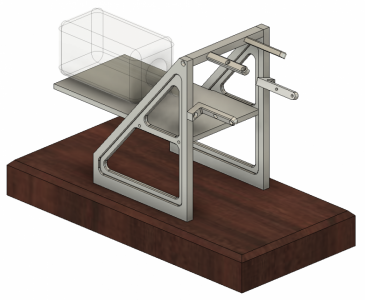
The shelf on the back is meant to hold (1) the fuel tank; (2) the oil tank; and (3) the battery box for the glow plugs. I’ve not yet made the shelf as of this post, but will probably knock it out tonight or tomorrow.
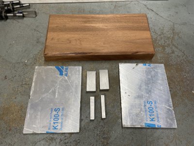
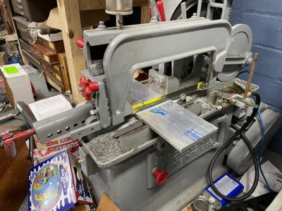
Here’s what I started with. The wood is Andiroba, which I’d never heard of before. It’s apparently in the mahogany family. My local lumberyard has a huge selection quality hardwoods. I found this piece in some of the offcuts for about $15. I trimmed it to size and cut the chamfers ‘off camera’ at my table saw. The aluminum plates were from a timely, and much-appreciated gift from a friend; I extracted them using my Peerless power hacksaw (don’t mind the empty beer cases strewn about -- those are a critical part of my process).
I didn’t get any pictures of the little brackets that attach directly to the crankcase. I got really annoyed making them, and had to make them twice due to a bonehead mistake on my part related to #4 vs #6 SHCS sizing.
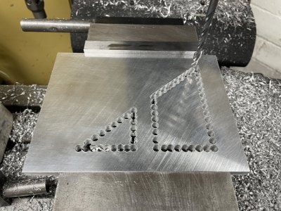
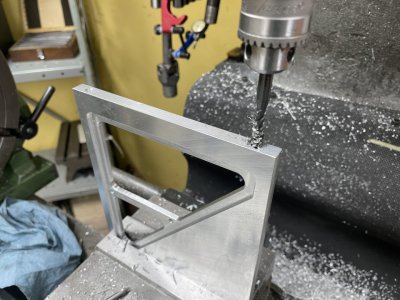
The triangular vertical plates were machined at the mill. After milling them to the correct overall size, I removed the bulk of the innards by chain drilling. Then I cleaned it up with a simple CNC program.
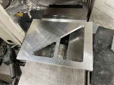
I used a couple more little CNC programs to mill out a step, then used a 90* single-flute chamfer cutter to cut a 0.040” chamfer around all the interior edges.
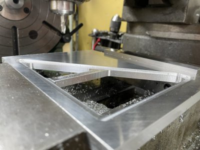
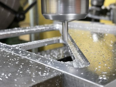
I had to flip the part and give the other side the same treatment. Things lined up perfectly. Then there were a few holes to drill/tap around the periphery.
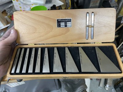
Chopping off all the excess material beyond the triangular shape was pretty straightforward, but required me to remove my milling vise and bolt the part directly to the table. This is the first time in about 3 years of owning my Bridgeport that I’ve removed the vise. I indicated things in using some new-to-me angle blocks.
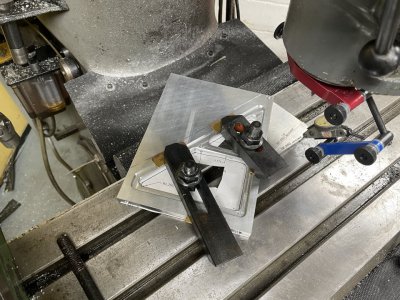
Then I just lopped off the extra to size by slotting with a 3/8” or so endmill.
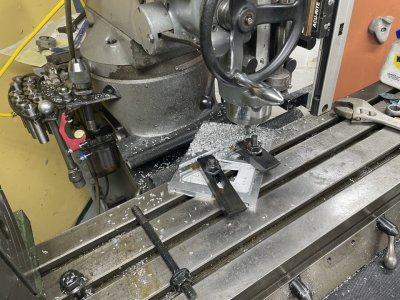
It took way more time to make the vertical pieces than these terse little paragraphs suggest.
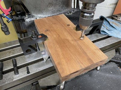
Then, because the mill vise was still off the table, I bolted down the chunk of wood after I’d finished with it at the table saw. Four holes and four counterbores (with a forstner bit) and it’s good to go. Most accurate holes in a chunk of wood that I’ve ever drilled.
I finished off the wood base with 3 coats of Old Masters Tung Oil Varnish (because I had it on hand). I might put some coats of regular clear varnish over the top to help add additional protection from oils and fuel and whatnot.
And here she is!!! Looks FANTASTIC (in my humble opinion).
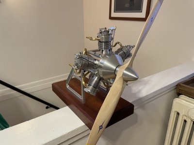
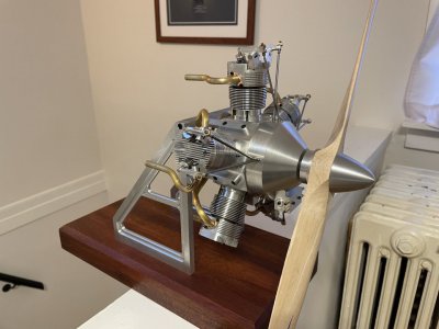
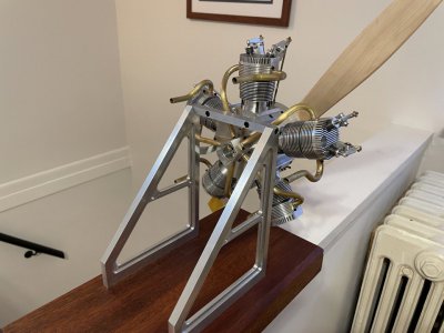
We’re closing in on a final product here. The to-do list still has quite a few items on it, but it at least fits on one small sheet of paper now. Probably a few items I’m missing on there, but you get the idea.
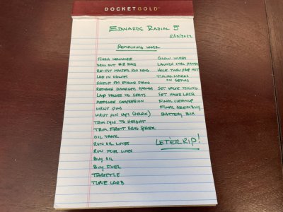
Still hoping to fire it up around the 4th of July, but any little hiccup will probably push that out.
TIME ON ENGINE STAND: 25.0 hours
CUMULATIVE TIME: 485 hours
As promised -- two posts in rapid succession.
This post gets me to a point that I’m pretty darn happy with. Quite frankly, if I were to stop here and not even try to fire it up, I could walk away a happy man. But I shall take it through to the end and get it running (I hope).
It took me seemingly forever to model up a stand that I liked in Fusion. But here it is. Some of the geometry is complicated because I’m basically translating the 10 facets of the crankcase into the two vertical stand components.


The shelf on the back is meant to hold (1) the fuel tank; (2) the oil tank; and (3) the battery box for the glow plugs. I’ve not yet made the shelf as of this post, but will probably knock it out tonight or tomorrow.
Here’s what I started with. The wood is Andiroba, which I’d never heard of before. It’s apparently in the mahogany family. My local lumberyard has a huge selection quality hardwoods. I found this piece in some of the offcuts for about $15. I trimmed it to size and cut the chamfers ‘off camera’ at my table saw. The aluminum plates were from a timely, and much-appreciated gift from a friend; I extracted them using my Peerless power hacksaw (don’t mind the empty beer cases strewn about -- those are a critical part of my process).


I didn’t get any pictures of the little brackets that attach directly to the crankcase. I got really annoyed making them, and had to make them twice due to a bonehead mistake on my part related to #4 vs #6 SHCS sizing.
The triangular vertical plates were machined at the mill. After milling them to the correct overall size, I removed the bulk of the innards by chain drilling. Then I cleaned it up with a simple CNC program.


I used a couple more little CNC programs to mill out a step, then used a 90* single-flute chamfer cutter to cut a 0.040” chamfer around all the interior edges.


I had to flip the part and give the other side the same treatment. Things lined up perfectly. Then there were a few holes to drill/tap around the periphery.

Chopping off all the excess material beyond the triangular shape was pretty straightforward, but required me to remove my milling vise and bolt the part directly to the table. This is the first time in about 3 years of owning my Bridgeport that I’ve removed the vise. I indicated things in using some new-to-me angle blocks.


Then I just lopped off the extra to size by slotting with a 3/8” or so endmill.

It took way more time to make the vertical pieces than these terse little paragraphs suggest.
Then, because the mill vise was still off the table, I bolted down the chunk of wood after I’d finished with it at the table saw. Four holes and four counterbores (with a forstner bit) and it’s good to go. Most accurate holes in a chunk of wood that I’ve ever drilled.

I finished off the wood base with 3 coats of Old Masters Tung Oil Varnish (because I had it on hand). I might put some coats of regular clear varnish over the top to help add additional protection from oils and fuel and whatnot.
And here she is!!! Looks FANTASTIC (in my humble opinion).


We’re closing in on a final product here. The to-do list still has quite a few items on it, but it at least fits on one small sheet of paper now. Probably a few items I’m missing on there, but you get the idea.

Still hoping to fire it up around the 4th of July, but any little hiccup will probably push that out.
TIME ON ENGINE STAND: 25.0 hours
CUMULATIVE TIME: 485 hours
