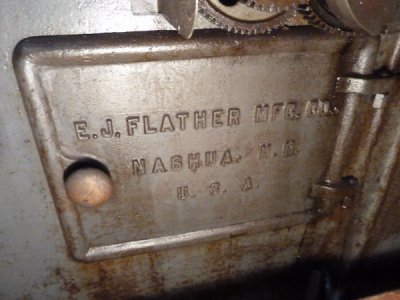
E.J. Flather Mfg. Co. Automatic Gear Cutter

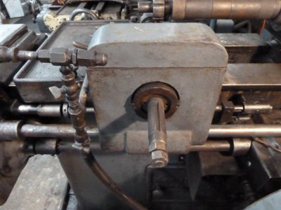
I am posting some details on my machine:
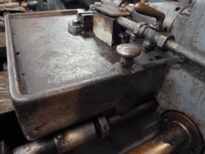
#1cutter arbor gearbox
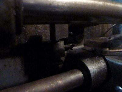
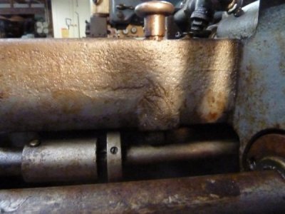
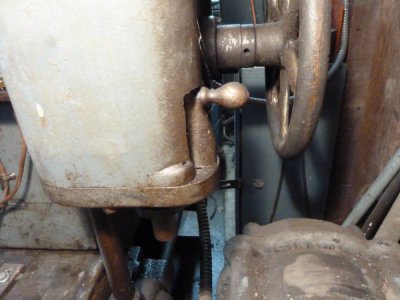
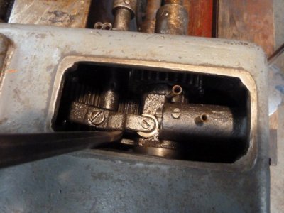
#2 feed return selector-- allows carriage to rapid travel all the way to the feed gearbox.
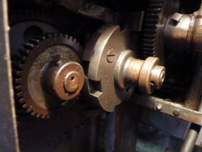
#3 index latch; when the pawl is withdrawn, it disengages the indexing motion.
#5 Index selector, when pulled out and rotated to different positions, it selects 1, 2, or 4 turns of the change gear input shaft.
# 6 Same as #2, but shows trip dog and striker.
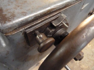
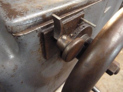
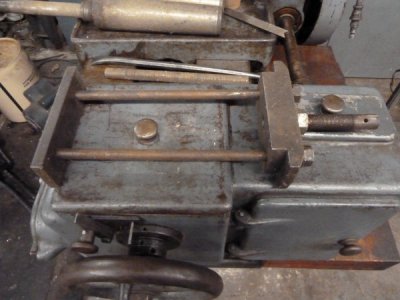
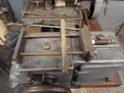
#7 latch on feed knob; when swung into position over the feed knob rod, it disengages the feed, it being necessary to lever the mechanism manually to accomplish the task; more on this later.
#8 shows the latch swung into position to disengage the feed; this can also be done by pushing/pulling the feed speed selector knob on the left side of the machine to an in between position.
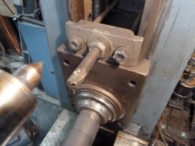
#9 shows the arbor support bracket; mine has just the one bolt to secure it, yours has 4 bolts in addition to the central bolt.
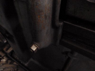
#10 Shows the index fine adjustment so that a gear may be perhaps recut after securing to the arbor, then lining up the tooth space with the cutter, also there is a bolt on the bottom, which when loosened allows the worm to be swung out of engagement with the worm gear.
gear cutter 001.JPG

gear cutter 002.JPG

gear cutter 003.JPG

gear cutter 005.JPG

gear cutter 006.JPG

gear cutter 007.JPG

gear cutter 008.JPG

gear cutter 009.JPG

gear cutter 010.JPG
 
I would think it ran off a line shaft and flat belt when it was new.

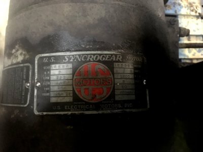
You are correct. Looking closer the motor was added. In this case a 2 HP gear motor putting out 232 RPM. It looks like the oil pump was added also.
IMG_3895.JPGIMG_3891[1].JPGIMG_3893[1].JPG

Welcome to the world of Flather! I have one exactly the same as yours, which I just got running again after a few years of not running. I have a chart of change gears for the indexing function that I could copy for you if you do not have one. I completely rebuilt mine many years ago, top to bottom. One thing to watch out for when preparing to start it up is to make sure the rotation is correct; just very briefly bump the switch on and off, and observe whether the cutter arbor rotates CCW when viewed from it's threaded end, things can get broken if it is allowed to rotate the wrong way, this I know from experience ----

Thank you John. I will send you a PM with my email address. I don't have any paperwork or charts, so anything will help. Classes start back up tomorrow and I'm heavily involved in FRC robotics, so it may be a while before I can get this off the pallet. Good note on the rotation. Fortunately the machine still had a cutter installed so I was planning on checking rotation against that. Thank you for the photos and the descriptions. Randy
 
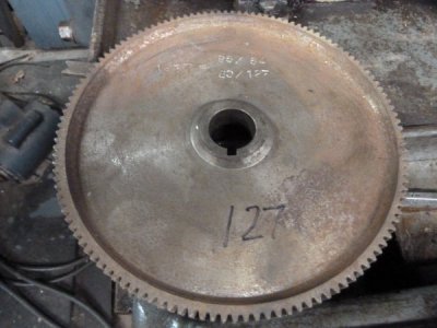
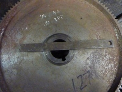
Looking at the pics again, I see that yours does not have a raised flange around the base to retain oil as does mine; I'm guessing that mine was perhaps built later, and was originally designed to cut steel as well as cast iron with a cutting oil circulating pump installed, it is gear driven, I was lucky to find a chart for a Brown & Sharpe auto gear cutter, the change gears are the same, but the Flather has twice the ratio in the worm gearing for indexing. Mine came with no change gears at all for speeds, feeds and dividing, I had to make them all on my milling machine. I also made some extras for prime numbers such as 127 for metric change gears and 119 for special leads. For the 127. I had to make a change gear with 127 tooth to fit the Flather having to cut the teeth in the mill using differential indexing, then I cut the larger. coarser gear for my lathe with the Flather.
 
wow. just wow. [envy]
 
Looking at the pics again, I see that yours does not have a raised flange around the base to retain oil as does mine; I'm guessing that mine was perhaps built late

Good eye. I see the lip in your photos. It has oil feed at the cutter... I guess I'll need to trace out the return path. It does have a chip trap on one side. I'll know more once I start cleaning. Maybe I'll try to take off right after classes tomorrow and dig a little deeper.
 
Who knows, do we have the only remaining examples of this POS of machinery in existence on earth?
 
Who knows, do we have the only remaining examples of this POS of machinery in existence on earth?

Maybe. At least now you found the second one they sold. :grin: I know back in the day this machine cut it's share of gears for the mills around here.

I wandered back to the shop tonight, pulled all the junk off the arbor, and took some more photos. I was able to turn the machine over by hand and it was fun to see it all turn. This machine sure has a lot of points to oil. Now I have even more questions.

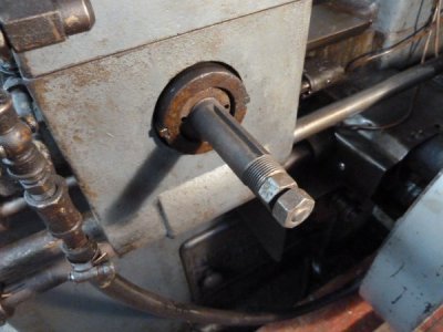
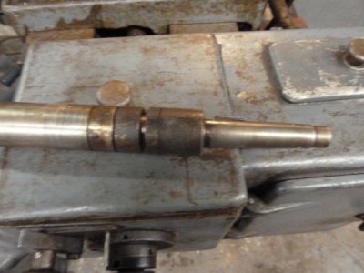
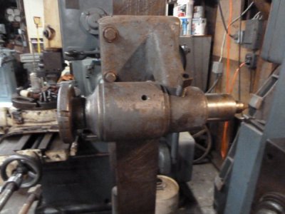
The arbor measured 1.5" and 1.75" on the shoulders behind the threaded section. Is the arbor interchangeable? It appears the spindle nose is threaded, possibly for a release nut?

What oil level do you suggest for the front gear boxes? I found two drain plugs in the bottom but not any oil.

Here are a few more photos. I'm missing the side door and instead there is a homemade box/chip pan plumbed into the oil pump. I looks like they've been cutting steel.
IMG_3899[1].JPGIMG_3900[1].JPGIMG_3901[1].JPG

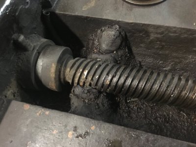
They put a dam at the head of the lead screw.
IMG_39031.JPG

This is the arbor. Does it go all the way though to the worm gear? Any provisions for smaller arbors? What are the threads for?
IMG_3902[1].JPG
 
I don't know if this will be of help: Gear Cutting Machinery dated 1909.
 

Attachments

  • Gear Cutting Machinery 1909.pdf
    25.4 MB · Views: 8
I don't know if this will be of help: Gear Cutting Machinery dated 1909.

Thanks for the download. The details are fairly thin but I did find the bevel gear cutter option for the machine on page 238 interesting.
 
Here are more pictures and commentary:
1 shows the shaft extension for pattern gear cutting
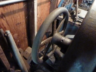
2 shows the handwheel in back that sucks in the arbor and also knocks it out
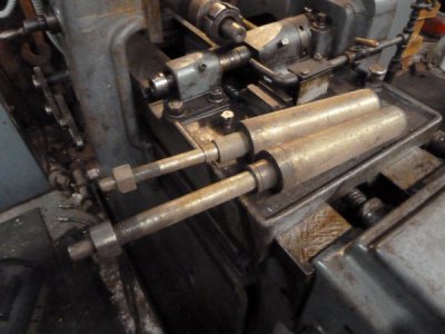
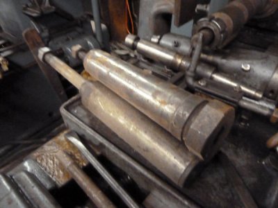
3 shows the arbors, 3/4", 1", and the 1 1/2" is in the machine
4 shows the cutter arbor for 7/8", the 1" is in the spindle; for 1 1/4" I use a flanged bushing with rectangular key
5 shows the outboard support bracket and center
6 shows the chip box door
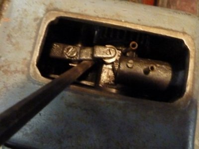
7 shows the toggling arm for the quick return/ feed, with a pry bar in place to toggle it over manually
8 shows it pried over with the feed knob catch in place to stop feeding
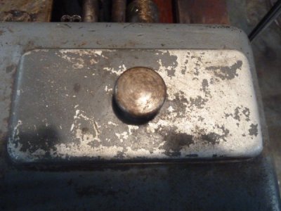
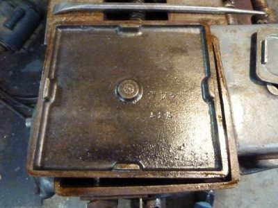
9 shows the cover for that compartment
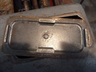
10 shows the cover upside down ( I have a foundry pattern for that part, I cast it in aluminum
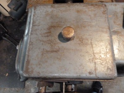
11 shows the cover for the other compartment
12 shows the underside of that cover
13 shows the steadying backstop to support the rim of the gear being cut, if it tends to chatter while cutting
14 shows a collet attachment so that pinions with integral shafts could be cut, or odd arbors could be inserted, it takes a #21 B&S collet
16 shows the backstop in place, but on top of the spindle for clarity; it is used under the spindle housing
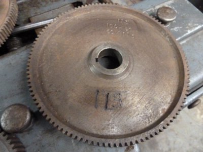
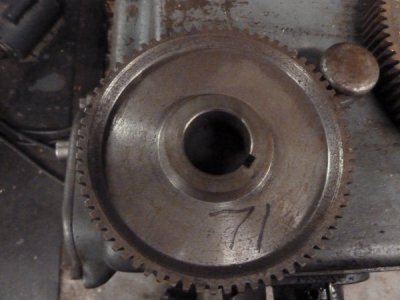
17 - 20 shows the extra change gears that I made for various prime number change gears, including 127 for metric transposing gears
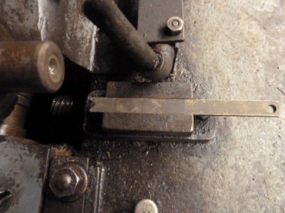
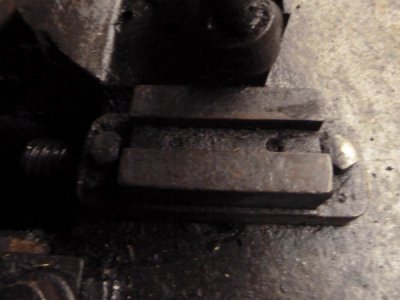
21 - 22 shows the gage used for centering the cutter on the arbor and it's receptacle bracket bolted to the carriage, it is simply a piece of flat bar with a vee accurately centered on the end

flather 1.JPG

flather 2 002 -.JPG

flather 2 003 .JPG

flather 2 004 .JPG

flather 2 005 .JPG

flather 2 006 .JPG

flather 2 007 .JPG

flather 2 008 .JPG

flather 2 009 .JPG

flather 2 010 .JPG

flather 2 011 .JPG

flather 2 012 .JPG

flather 2 013 .JPG

flather 2 014 .JPG

flather 2 015 .JPG

flaher 2 .JPG

flather 2 017.JPG

flather 2 018.JPG

flather 2 019.JPG

flather 2 020.JPG

flather 2 021.JPG

flather 2 022.JPG
 
Back
Top