- Joined
- Jul 15, 2020
- Messages
- 421
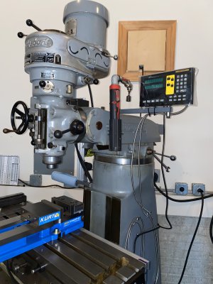
I wanted to share a few thoughts based on my DRO-PRO EL-400 install. Their web site has a number of well done how-to videos, but the mill they use is a small benchtop model that has few similarities with a Bridgeport or clone. Here are a few obstacles I encountered, and my solutions for what the might be worth.
My 1969 Bridgeport J Head model has been around the block a few times, and has a number of small drilled and tapped holes all over the place. My goal was to use as many of these as possible, so as to avoid having to make new ones. Based on some existing holes, It appeared to have had a DRO on it at some point, but I have no idea what kind. Naturally, none of the holes lined up with anything in the DRO-PRO kit.
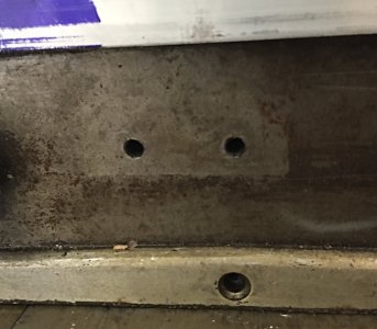
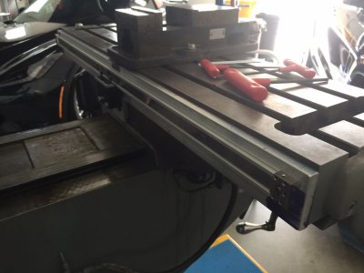
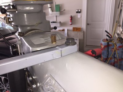
I reasoned that I preferred to drill and tap holes in a new bracket on a drill press rather than on the table of my mill. That way I could insure that the holes went in straight, and the threads went into the holes straight. I fabricated a 2 1/2" x 1/2" aluminum bar the same length as my table, which happened to be just 1/2" longer than the DRO-PRO X axis scale. I drilled the bar to match 3 existing holes in the back of the table, and drilled and tapped a hole in each end to match the bolt pattern on the ends of the scale. The center hole of the 3 had to be countersunk, which is why I needed the bar to be 1/2" thick. I covered up the two coolant drain holes at the ends of the table, since I have no intention of ever connecting plumbing to them or otherwise using them.
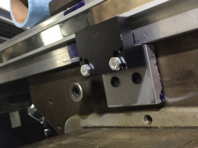
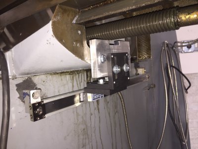
There were two existing threaded holes in the rear of the saddle at its center. I fabricated a bracket 1/2" thick to space the reader head out the same distance from the table as the scale, and to adapt the reading head mounting bracket provided by DRO-PRO to the holes in the saddle.
For the Y axis, I used two exiting holes in the side of the knee which had apparently been used previously for a DRO scale. I made a couple of small spacer blocks, and a bracket to adapt two existing holes in the underside end of the table to the bracket supplied by DRO-PRO. I cut off a leg of one of the DRO-PRO brackets that was not necessary. I ended up not having to cut either of the magnetic scales from their original 12" x 30" length (my mill has a 9" x 36" table).
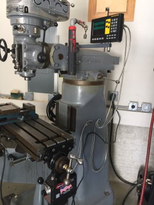
The cables provided by DRO-PRO were at least 3 feet too long, so I utilized some existing 1/4" x 20 holes in the side of my mill's base for some imaginative cable routing, and to avoid the full weight of the cables hanging on the display monitor connections.
The display mounting arm provided by DRO-PRO was kind of Mickey Mouse and could not be easily attached to a Bridgeport. I fabricated a 1" x 1/8" wall length of square tubing 15" long to support the display. When I bolted it to the 5/8" diameter hole in the top of the ram, it had a downward angle, so I sawed a slot down to the bottom of the tubing, bent it shut, and welded it to make it level.
This isn't a whole lot of information - just what happens to come to mind. One last thought: when you use the .020" shim to get the correct clearance on the reader heads don't make the mistake of removing the scrapers to do it. You'll find it next to impossible to re-install them with the reader heads attached to the mill.
My 1969 Bridgeport J Head model has been around the block a few times, and has a number of small drilled and tapped holes all over the place. My goal was to use as many of these as possible, so as to avoid having to make new ones. Based on some existing holes, It appeared to have had a DRO on it at some point, but I have no idea what kind. Naturally, none of the holes lined up with anything in the DRO-PRO kit.
I reasoned that I preferred to drill and tap holes in a new bracket on a drill press rather than on the table of my mill. That way I could insure that the holes went in straight, and the threads went into the holes straight. I fabricated a 2 1/2" x 1/2" aluminum bar the same length as my table, which happened to be just 1/2" longer than the DRO-PRO X axis scale. I drilled the bar to match 3 existing holes in the back of the table, and drilled and tapped a hole in each end to match the bolt pattern on the ends of the scale. The center hole of the 3 had to be countersunk, which is why I needed the bar to be 1/2" thick. I covered up the two coolant drain holes at the ends of the table, since I have no intention of ever connecting plumbing to them or otherwise using them.
There were two existing threaded holes in the rear of the saddle at its center. I fabricated a bracket 1/2" thick to space the reader head out the same distance from the table as the scale, and to adapt the reading head mounting bracket provided by DRO-PRO to the holes in the saddle.
For the Y axis, I used two exiting holes in the side of the knee which had apparently been used previously for a DRO scale. I made a couple of small spacer blocks, and a bracket to adapt two existing holes in the underside end of the table to the bracket supplied by DRO-PRO. I cut off a leg of one of the DRO-PRO brackets that was not necessary. I ended up not having to cut either of the magnetic scales from their original 12" x 30" length (my mill has a 9" x 36" table).
The cables provided by DRO-PRO were at least 3 feet too long, so I utilized some existing 1/4" x 20 holes in the side of my mill's base for some imaginative cable routing, and to avoid the full weight of the cables hanging on the display monitor connections.
The display mounting arm provided by DRO-PRO was kind of Mickey Mouse and could not be easily attached to a Bridgeport. I fabricated a 1" x 1/8" wall length of square tubing 15" long to support the display. When I bolted it to the 5/8" diameter hole in the top of the ram, it had a downward angle, so I sawed a slot down to the bottom of the tubing, bent it shut, and welded it to make it level.
This isn't a whole lot of information - just what happens to come to mind. One last thought: when you use the .020" shim to get the correct clearance on the reader heads don't make the mistake of removing the scrapers to do it. You'll find it next to impossible to re-install them with the reader heads attached to the mill.
Attachments
Last edited: