DRO Install on a Clausing 4900 Series Lathe

Kennyd

Active User
Registered
Joined
May 1, 2011
Messages
484
I will use this thread to document the entire install. I am doing 5 other major projects also so it may take a little while to complete.

This is a follow up from these threads: http://hobby-machinist.com/index.php?topic=2850.msg19687#msg19687 and http://hobby-machinist.com/index.php?topic=2019.msg13125#msg13125


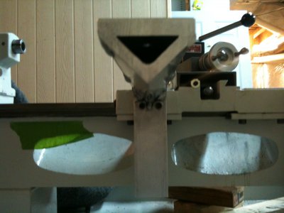
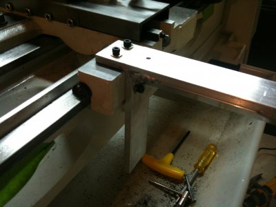
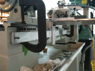
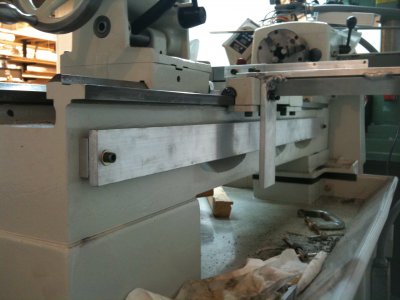
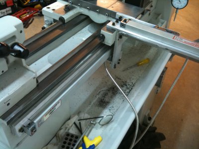
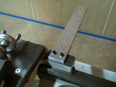
As posted in the other threads, I could not mount it in a conventional manner due to the gib adjustment screws being in the way, I needed to hang it off the back somehow. So using some 3/8" x 2" flat AL bar, I made the main part of the mount, the lower leg will hold the reader head for the long slide. Then I added 1 1/4" x 1/4" angle to the underside for support and welded it with my Miller MIG and spoolgun. The welds are very ugly-I have little practice with welding AL so I dressed them up a little with JB weld so it will look nice when it all painted. I do have plenty of penetration though as evident by the end I cut off.

I then drilled and tapped the 1/4-20 holes to hold the mount, it is VERY sturdy. Next I made the 1/4" x 3/4" bar to move the reader-head, Again I drilled and tapped 1/4-20 holes to mount it.

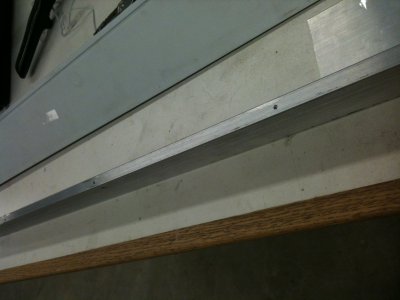
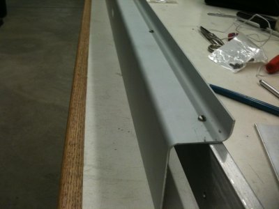
Here are the pictures of the progress so far:
IMG_1023.jpg IMG_1024.jpg IMG_1025.jpg IMG_1026.jpg IMG_1027.jpg
 
Last edited by a moderator:
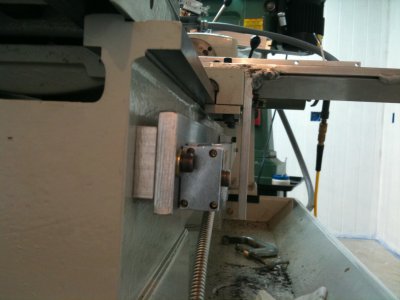
I like that a lot. I solves my biggest issue with cross slide DROs - cluttering the workspace and adding a swarf collection area.
This is the digital version of what I used to do with a dial indicator on a heavy base behind the cross-slide.
 
Kenny, looking great so far.

Awaiting more when you clear your plate a bit.

Thanks,


Nelson
 
AR and Nelson, Thank you very much!

Tonight I got a little more done instead of painting the walls in the workshop again like I should have been doing :crying: I sure hate painting...

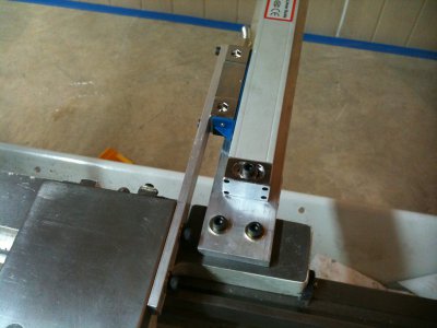
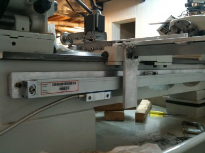
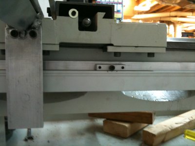
I started mounting the Z scale, I first cut the 2"x3/8" flat bar to length, then drilled the two mounting holes. Next I clamped it under the rear way using 123 blocks to space it 1" from the way.

Then I used a transfer punch to mark the holes on the bed-then drilled and tapped them 1/4-20. The bar is held off of the bed with 10mm spacers that came in the DRO kit.

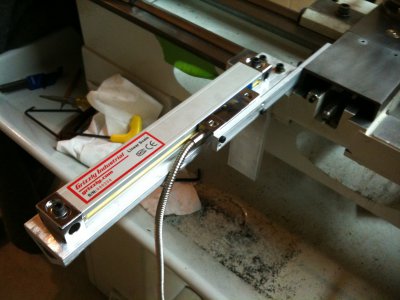
Then I drilled and tapped the holes (1/4-20 again) to mount the scale to the bar, and also added one of the included dovetailed supports in the middle of the scale.

That's as far as I got...Still need to make the bracket to connect to the reader head but that should be easy, and attach the scale shield to the flat bar. Then I will media blast everything and paint it before the final mounting and adjustments.

Tomorrow I MUST paint, Tomorrow I MUST paint, Tomorrow I MUST paint, Tomorrow I MUST paint, Tomorrow I MUST paint, Tomorrow I MUST paint!

IMG_1028.jpg IMG_1029.jpg IMG_1030.jpg IMG_1031.jpg IMG_1032.jpg
 
Last edited by a moderator:
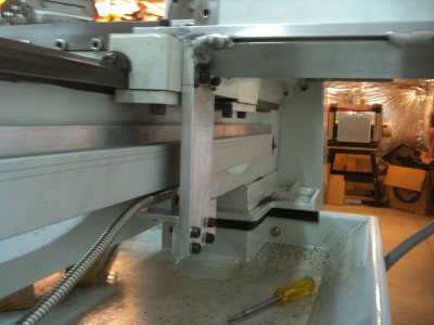
Good work- keep it up!

Too humid here to paint, I like much less humidity to help the paint dry. NYC is notorious for this humid weather.


Nelson
 
Allthumbz link=topic=2937.msg21118#msg21118 date=1312649770 said:
Good work- keep it up!

Too humid here to paint, I like much less humidity to help the paint dry. NYC is notorious for this humid weather.


Nelson

Oh...We have humidity here also! But in the basement it stay's about 68* and low humidity. I got one more coat done today-hope to finish in the morning.
 
Last edited by a moderator:
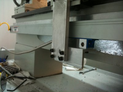
Looking a very tidy install...

I install quite a few DRO's, one thing worth doing is running a DTI mounted on the lathe carriage against the scale to check alignment - with casting draft and such the mounting face doesn't always run exactly parallel to the ways (I usually aim for a max of 0.003" out of true end to end, vertical and horizontal). If adjustment's needed, drill and tap the mounting bar for a couple of jackscrews at each end (e.g. 1/8 or 3/16 NF grubscrews) above and below the fixing screws, this'll allow you to bring it exactly parallel to the ways in the horizontal plane (viewed from above) and eliminate any twist due to the bed casting not being completely flat, for the vertical plane the slotted holes allow gentle tapping into place with your lightest plastic hammer! - the glass scales can handle a small* amount of end-to-end divergence, but not a lot, too much can affect accuracy or even crack the glass...

Dave H. (The other one!)
 
Hopefuldave link=topic=2937.msg21388#msg21388 date=1312847647 said:
Looking a very tidy install...

I install quite a few DRO's, one thing worth doing is running a DTI mounted on the lathe carriage against the scale to check alignment - with casting draft and such the mounting face doesn't always run exactly parallel to the ways (I usually aim for a max of 0.003" out of true end to end, vertical and horizontal). If adjustment's needed, drill and tap the mounting bar for a couple of jackscrews at each end (e.g. 1/8 or 3/16 NF grubscrews) above and below the fixing screws, this'll allow you to bring it exactly parallel to the ways in the horizontal plane (viewed from above) and eliminate any twist due to the bed casting not being completely flat, for the vertical plane the slotted holes allow gentle tapping into place with your lightest plastic hammer! - the glass scales can handle a small* amount of end-to-end divergence, but not a lot, too much can affect accuracy or even crack the glass...

Dave H. (The other one!)

Thanks Other Dave, I understand the alignment issues and will be working on that next-right now I am trying to get all the rough in work completed. All the holes are slightly oversized to allow for small adjustments, and the end caps on the scales are slotted as well.

I worked a little yesterday on the reader head attachment, but forgot to take pictures :(

But the good news all the painting in the shop is done :)
 
Last edited by a moderator:
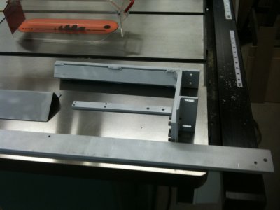
More progress...

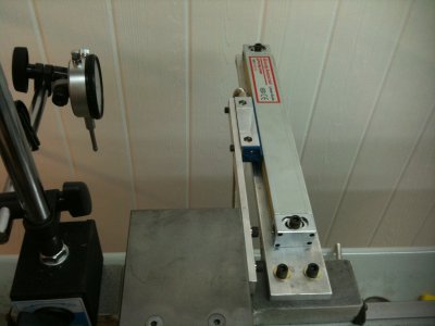
All the mounts are completed. I had everything mounted and dialed in to unsure it was all going to work and so far the project is a success.

Then I took it all off, and added the scale guard to the top edge of the 3/8"x2" flat bar with 4-40 screws, and finally Imedia-blasted everything (last picture) then primed and painted with Krylon Satin Black (no pictures of that yet...)

IMG_1039.jpg IMG_1040.jpg IMG_1043.jpg IMG_1037.jpg IMG_1038.jpg IMG_1041.jpg IMG_1042.jpg
 
Last edited by a moderator:
Back
Top