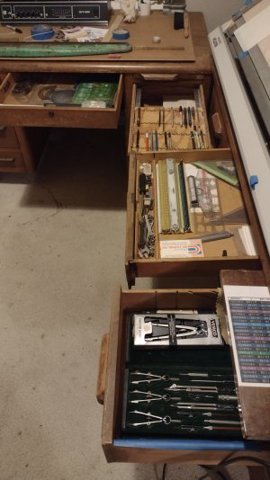
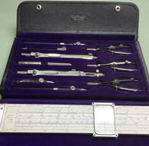
I took drafting all four years in H.S. with the intention of becoming a draftsman as a profession. I had also taken a college prep route and entered college on an engineering track which transitioned to degrees in the hard sciences For the next thirty years, I used my drafting skills in my business. When I began a new career as a manufacturing engineering manager for a medical device company, I started using CAD as an efficient way to express ideas to our draftsman. This was first done with Vellum, then an Autodesk product called AutoSketch, and finally AutoCAD. In 2004, I started working with SolidWorks. The learning curve was a bit steep but the clear advantages of a parametric CAD system quickly outstripped the downside.
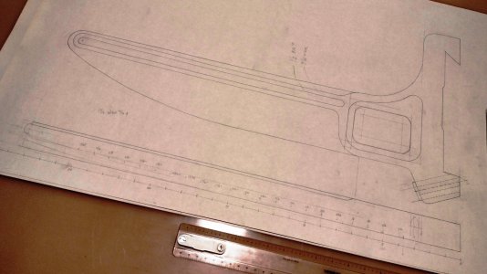
In using mechanical drafting, one has to have a clear idea as to the final design in order to be efficient. This usually involves having fairly detailed sketches beforehand. With parametric CAD, a redesign can be accomplished as simply as changing a dimension or pulling a feature with a mouse. I still have my drafting equipment but haven't used it in years. I use an eraser perhaps a few times in a year.
Below is an example of a fixture I designed for under cabinet lighting in out kitchen. It is designed to fit tight behind the facings of the cabinets so as to be out of sight. There are fourteen sections of these fixtures, with each one being unique. The most complex of these fit elliptical facings. The front surface of the facing is a true ellipse which means that the back surface is offset from the ellipse and the abutting fixture is offset from that surface. These curves aren't true ellipses and are mathematically quite complex. If I was drawing these features, I would have to offset multiple points with my compass and use a French curve to approximate the curves. With SolidWorks, one simply clicks on the Offset tool. selects the curve to offset, and enters the offset distance.
Even if I had successfully drawn the parts, converting them to something useful for machining. These parts were the main driver for my purchasing my Tormach CNC as I could think of no other way to make them. The CAM package that I purchased with the CNC effortlessly converted the CAD models to G code. The work envelope of the CNC required breaking the fixtures into manageable sections and there was machining on both front and back sides. To accomplish this, I positioned holes for 3/16" dowel pins in my new CNC table and used used a sub-plate with holes for dowel pins to fit holes in the parts which also served as mounting holes for the completed parts. Even at that, the parts had to be oriented on the sub-plate to fit the work envelope.
Were I working with mechanical drafting, assuming that I could determine accurate coordinates for the dowel pin holes, I would have to got though a a mathematically complex rotation of the locating holes in my sub-plate. This would have been a daunting task and more than likely, I wouldn't have undertaken it.
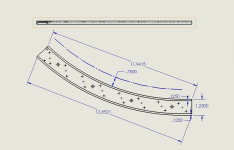
The blue construction line is the elliptical curve representing the location of the front of the cabinet facing. All other curves are offsets front that curve.
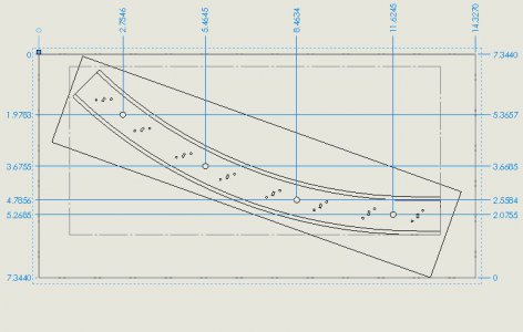
This is the layout for machining one of the larger sections. The large rectangle is the travel extents of the Tormach CNC. The small rectangle is the outline of the raw stock, 1/4" x 3" 6061 aluminum. The blue coordinates listed are the location of the dowel pins used to fix the part on the sub-plate.
