Double Lead Left Hand Acme

eightball

Active User
Registered
Joined
Jan 2, 2013
Messages
226
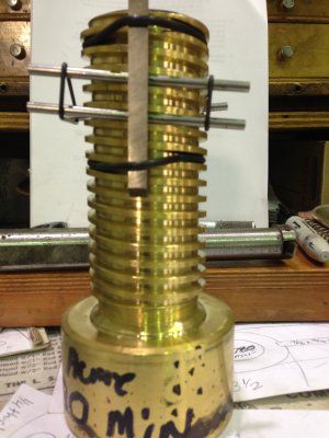
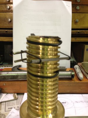
Hi everyone, Had to make another double lead left hand acme nut again. I've made a couple of these nuts over the last 15 years or so. Problem is, I had to fit them to a valve stem about a mile away from the shop. So this time i made a test plug. Thought i'd try to post a couple of pics. I measured the stem over wires on both leads. Fortunantly they were the same. I made this one with the pitch dia. about .002 thou bigger. My nut fit perfectly on the first try. this shaft is 2 inch dia. with a double lead #4 left hand acme thread. I made my nut out of everdur which should hold up well. The test plug was just a piece of bronze i had laying around. If anyone is interested i can try to take pics of the method i used to measure pitch dia. I was well pleased with the result. I threaded both parts on a tool mex lathe, and split the thread instead of doing one thread at a time. I find it less time consuming and more accurate to do it that way.
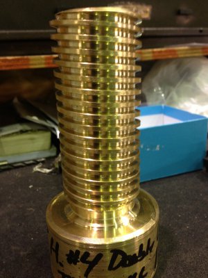
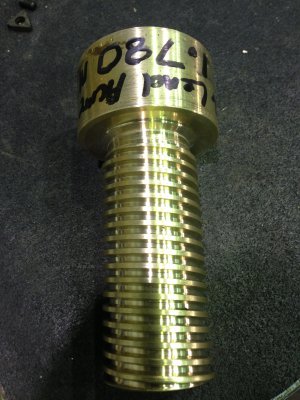
eightball pics 014.JPG eightball pics 015.JPG
 
Last edited:
Well done and please post the pics. Also for those not in the know explain what is meant by "Double Lead" and why it was needed. This will make for a very interesting and informative thread.

"Billy G"
 
A double lead thread has two seperate threads 180 degrees apart. So measuring them is a little different than just measuring a single lead thread. You have two seperate threads so i measure the pitch dia on both threads. I have made these before by turning my compound parallel to the work. I do this with an indicator to make sure its exactly even. Then i have cut one thread to depth, then dialed over one half the lead and cut the other thread. The lead on a number 4 acme is .250. However with a double lead its double that or .500. So i set my lathe on 2 theads per inch. Being old school i like to set my compound at 14 degrees and feed in on compound. This tool mex lathe has 8 lines, so i cut the first thread by engaging on a line, and the second thread by engaging between the lines. You can mark these (half lines) with a sharpie if you desire. Doing it this way , you feed in evenly on compound til you acheive your desired pitch dia. When turning the compound 180 to work, I always cut a 60 degree v thread first. That way your not getting so much chatter and taking such a huge cut with an acme cutter. When making my nut i usally undercut a small amount to just under the finish diameter of the screw. That way i know when im close to my pitch dia. I then start trying my test plug. I've been doing this for a long time and its really easier for me to make the part than try to explain it. BTW this is my first time to post a pic. If this in any way helps someone, I'd be more than glad to show you. Tomorrow, If i get a chance, I will take a pic of my wires and tool steel that i used to measure the pitch. Looking at that pic should help you understand better the two seperate threads and the reason the lead is double the pitch. And thank you Bill for your reply. As you can see I havent been on this site long. I'm still learning to post so please just bear with me. The reason for a double lead is that one revolution of the shaft moves the nut twice as far. I have cut triple lead threads also.
 
Last edited:
Great explanation and description, Eightball, splitting th lines hadn't occurred to me!

I've always cut multiple starts by "walking the spindle", I'll try to explain...

Set up the change-gears or QCGB for the desired lead, eg 2 tpi as your example, be sure the spindle gear has a tooth-count divisible by the number of starts - eg a 36 tooth spindle gear works for 2, 3, 4, 6, 9, 12 or 18 starts (heaven forbid...), and cut the first start to full depth.

Now, mark all the change-gears with a paint stick where they mesh, release the quadrant and rotate the spindle and its gear through teeth/starts and mesh the quadrant gear to it - be sure the other gears are still in the marked meshed position! For instance, with a 36 tooth for 2 starts count round 18, for 3 starts 12 etc.

This puts the spindle at the correct position to cut the next start using the same line on the thread dial and, more importantly, allows cutting non-native threads with multiple starts, eg a metric trapezoid (Europe's Acme), by the "nuts engaged, forward and reverse" on an inch leadscrew lathe...

Just thought I'd pass on another method that has worked well for me,

Dave H. (the other one)
 
Dave, I understand your method but my problem with that would be that i cant see the change gears on the lathe. They are on the headstock at end of lathe and all covers have to be in place for it to run. (limit switch) Yes i could jump the limit but i wouldnt be able to see the marks on my gears. The Monarch lathe is even worse. I do have to change my gears in the tool mex and its very simple to do, to do 2 threads per inch. But i have never had a problem splitting an acme thread. I already expained an even thread but an odd number of threads is even easier. ( Catch an even line one pass and an odd line the next) With more than 2 leads i can see how your method would be superior. when i do a triple lead i use the compound at 180 and dial over the pitch dia. Please understand im not saying the way i do this is any better or worse, its just easier on me with the equipment I have. I appreciate anything that gives me an alternative method. If you have never tried cutting a v thread first, it works very well. Like i said earlier, ill try to take pics of my thread measuring wires in place on this test plug and hopefully ppl that hate measuring over wires will see how easy it actually is.Ive never had thread mic's and really see no need for them because i dont do this very often. Thanks for your comments.
 
eightball pics 003.JPGeightball pics 001.JPGeightball pics 004.JPGeightball pics 002.JPGeightball pics 005.JPG


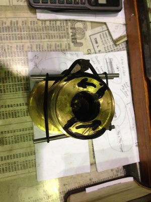
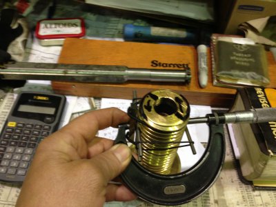
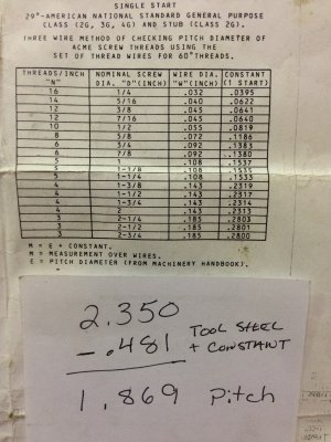
ok, ill try to explain how i measured the pitch dia. on this double lead thread. When using the 3 wire method on a single lead its simple. I place my anvil across the two wires and sweep the single wire with the thimble. On a double lead, because of the distance between the wires, you need something to bridge the gap. In this case i used a piece of 1/4 hss. I also downloaded the chart with the constant for figuring pitch dia. I simply add the thickness of the tool steel. There are a lot of ways you can hold your wires but this is hands free.I also have one pic of the end of the shaft. the line across is where the two seperate threads start. I tried to highlight the beginning of each thread so you can see there are indeed two seperate threads. Hope this helps.

eightball pics 001.JPG eightball pics 003.JPG eightball pics 004.JPG eightball pics 002.JPG eightball pics 005.JPG
 
Well, I have to make another one. This time i,ll take pics while i make the actuall nut. Its for an automatic valve actuator.
 
There is a difference in the calculation of the MOW figure for multi-start threads, of any type. The helix angle is compensated for in the standard charts for the constant given, but it is for a single start thread only. Granted, it's not a lot, but the coarser the pitch, and the more starts there are, the greater the effect.

When I've cut multi-start threads on a manual machine, I have always used the setover method with the compound set parallel with the spindle axis. Of course, this requires that the thread be cut by direct plunge, and not by using the 29.5° (or appropriate angle) incline of the compound. I've never had a problem because of that, though. Of course, if threading to a shoulder, or a specified pullout point, the stop, or indicator must be adjusted to compensate for the new tool position.

On NC/CNC equipment, it's much simpler, of course, but the principle is the same. One company I did work for had a series or parts that were threaded on both ends, one a single lead, and the other a double lead (or 2 start, depending on what terminology you prefer) to create different makeup positions for bent motor housings. The two housings being coupled had matching threads in the ID. Typical sizes ranged from about 4 3/4 to 10" diameter. Sort of difficult to describe, but if there are any of you guys familiar with directional drilling using mud motors, you probably know what I am talking about.
 
You are absolutely correct Tony. I feel certain you are more familiar with multiple thread starts than I am. I was doing a comparison measurement , so I wasn't worried about the difference of the actual pitch to what I was getting, as long as it was the same. The only difficulty I had was the threads in the valve stem were a little shallow. Pitch was same in stem and my test plug but I had to bore the I'd of the nut a little larger
 
That's one thing to watch out for. For example, offsetting the tool in -Z- to split the thread also allows you to use the wrong insert but get the correct root width. You can cut a 6 pitch double lead with an 8 pitch or 10 pitch insert, provided it is not a topping insert. But in order to do that, you must know and establish the minor diameter as a separate feature. This applies to any Acme or Stub Acme thread. Once you get to the proper thread depth, as determined by the minor diameter, you can move the insert over the correct amount to compensate for the undersized nose width and still make a correct thread. Also to be noted is that the insert is different for internal vs external threads on the root width.

I'd guess that you had an internal insert and cut an external thread (if I remember right, the internal root is wider). This means you would hit the PD before you hit the minor. That could potentially interfere with the clearance needed between the minor diameters of the parts. I'd bet if you measured the minor of the parts you made, it would be a little oversized and hence required you to open up the minor of the nut, the easiest fix.

I can run a Gagemaker data sheet with all the specifics and tolerances if you'd like. All I need is the nominal thread size, pitch, and number of starts. It will give you all the details of both the internal and external threads. And if you know the wire size, it will calculate the MOW as well.
 
Back
Top