Does Cnc Backlash Compensation Really Work?

j ferguson

Active User
Registered
Joined
Nov 28, 2013
Messages
196
I suppose I'll find out for myself soon enough, but after a serious amount of messing with the Z-Axis backlash on my new sherline 2000, I got it down to .003. I can't get it any farther without incurring binding.

I can see how backlash compensation in the CNC config file should work, but does it? I assume it must assume .003 movement of lead screw before it also assumes saddle has moved.

Am i missing anything?
I just looked at the Mach 3 manual and their controller compensates for backlash by approaching a position from the same direction. This works for drilling holes but cannot compensate for movements while profiling such as pocketing etc.

It would seem to me that a better way would be to compensate for lash whenever you changed direction.
 
I would think that the best way would be to bias the Z up with a counter weight or an air spring. An air spring might be the best in that it adds the least mass to the system. While I don't have a sherline, I do have an air spring on mine and have zero lash on the Z.
 
Hi Jim,
I'd thought of something like this. How did you choose the specs for your spring?
 
Most of it was a seat-of-the-pants calculation. I weighed the quill by placing a bathroom scale on the table and removed the return spring. Then just set the quill down on the scale. I think it was about 30 lbs or so. I just decided to add about 20 lbs of bias to that, for a total of about 50 lbs of up bias.

Then I chose an air cylinder that would give me that amount of pull at about 35 PSI. A 1 1/2 inch bore cylinder was in the range I wanted. Then I used a cable system to attach to the cylinder. One of the keys to this system is to have a large volume of air available directly to the cylinder. Just a regulator will not maintain a constant pressure as the cylinder volume changes due to the movement, so what I did was Tee a Harbor Freight portable air tank with the cylinder, after the regulator to keep a nearly constant pressure on the system.

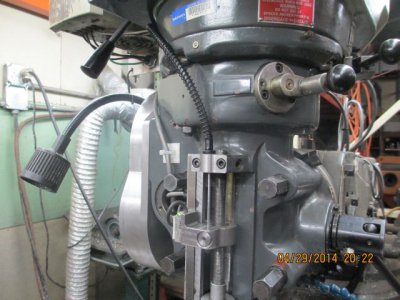
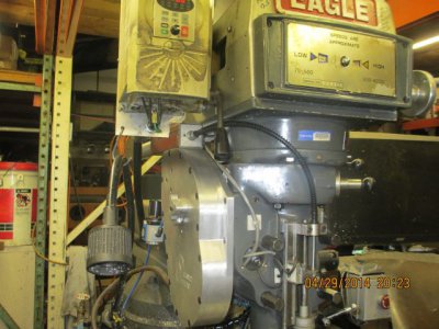
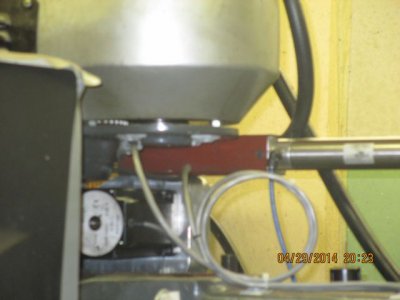
This is how I attached to the quill, the cable is a modified Yahama Banshee brake cable. Your installation will be completely different, but the same principles will apply.
counterbal1.jpg


counterbal2.jpg

counterbal3.jpg
 
I don't have a Sherline, so I am not familiar with your nut and screw. I have a Seig X2, which is a real pig. I used a setup similar to Hoss, but with a delrin anti-backlash nut on an acme screw for the Z instead of a ballscrew. I have no measurable backlash. You might want to look into improving your nut, screw, or both.

I have just moved from Mach3 to LinuxCNC, so my current backlash strategy wouldn't help. I am also milling wood right now, so I haven't even looked at that part of the calibration. When I was running Mach3, my X backlash compensation was 4 and my Y compensation was 7. It seemed to work for the level of accuracy I needed for the aluminum and steel parts I made.

Larry
 
Most of it was a seat-of-the-pants calculation. I weighed the quill by placing a bathroom scale on the table and removed the return spring. Then just set the quill down on the scale. I think it was about 30 lbs or so. I just decided to add about 20 lbs of bias to that, for a total of about 50 lbs of up bias.
Jim, Out of curiosity, why did you choose to bias upward rather than downward? The unmodified downward gravitational force of 30 lbs. apparently is not enough to overcome frictional forces in the ways; otherwise the head would drop to its lowest possible position. It would seem that the best solution would be to provide additional downward force via the cylinder.
I would expect that under certain operations like drilling, the cutting pressure could be sufficient to lift the head against that force but for light duty operations like 3D contouring, where the head is moving in both directions, I expect that gravity and the cylinder force would overcome any effect from cutting pressure.


I thought long and hard about this when I was designing the conversion. In a stock BP type mill the quill will just drop if it is not biased by the return spring, and I assume that the Sherline Z-Axis would just drop if not held by the lead screw. There is also about 0.020 backlash in the rack & pinion that moves the quill. To overcome this backlash, and to take out any backlash in the gear train biasing upward was the best way to control everything.

The vertical cutting pressure is normally substantially greater than the weight of the quill so it is biased upward by the operation, but if you are doing a light operation, the quill would float as you described. Thus the accuracy would be compromised by the float. My Z holds 0.0001 consistently.

By biasing upward, gravity and cutting pressure is taken out of the equation and thus you have a solid, zero lash mechanical connection to the drive. In the case of your Sherline, the system backlash is substantially less than what I had to deal with, but I think the same principal applies. Another consideration was the mechanical installation, it was cleaner to put the system under tension rather than figure out how to mount a cylinder on the head to provide down force which requires a direct, in-line, connection between the cylinder and the quill.
 
I used backlash comp in LinuxCNC before I had preloaded screws. Originally I was using the stock acme screws which had about 0.014" of backlash. The compensation worked pretty well, though keep in mind that it doesn't allow you to climb mill like a pre-loaded nut would, it just helps you keep on size. I also found that I had to take an extra cleanup pass as heavy cuts would pull the table out of position. I ran this way for a year and a half with good results.
 
Jim, The Sherline head is pretty light relative to friction in the leadscrew nut setup which means it doesn't automatically drop, at meast mine doesn't. The Z-Axis way geometry is such that installing a pre-loaded nut would be difficult maybe impossible. A guy who makes a lot of U-Tube videos of his very clever Sherline mods is also refreshingly honest and posts more detail when it turns out that the thing didn't work over the long haul.

I, too, am using LinuxCNC and am glad to see that backlash comp worked for DMS. I have plenty of time to make things, so I generally make a couple of very light passes at the end of a run to remove any trace of earlier enthusiasm.
 
Back
Top