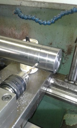
Cutting square shaped spiral

FTlatheworks

Registered
Registered
Joined
Apr 24, 2021
Messages
462
Is it possible to cut a spiral type pattern/design on bar stock in a lathe?

I was thinking, If I were to use a square thread cutting tool, then choose the coarsest thread setting, would I be able to make a spiral type cut/pattern on a part?
 
I don’t think that would do what you’re imagining.
But supposing you had a piece of square bar that you wanted to turn into a spiral shaped square, there’s a recipe for that. Start with fire, heat to bright red, add twist.
That recipe is as old as the smithing trade, and there really isn’t a “better” way.

 
Yes, you would, as long as the generated spiral pitch will be what you need and the part will not deflect (use a follower rest). If you need a pattern with multiple spirals then the part will require some form of indexing. Different (non-standard) pitches can be achieved on a manual lathe by using custom change gears. You should consider that such a cut will use a considerable force, so the lathe should be capable of doing it.
 
A true square spiral will require a very specifically ground toolbit.

It will need the same helix as the groove ground into it or the heel of the bit will interfere before you get very deep.

You could go with simply using a massive amount of clearance, but you would be gambling that there was then enough support for the cutting action.
Yes, you would, as long as the generated spiral pitch will be what you need and the part will not deflect (use a follower rest). If you need a pattern with multiple spirals then the part will require some form of indexing. Different (non-standard) pitches can be achieved on a manual lathe by using custom change gears. You should consider that such a cut will use a considerable force, so the lathe should be capable of doing it.
Here is a thread of a cross drilling fixture using a boring bar holder. How did he do the spiral pattern he’s got going on if you had to guess?


Can anyone shed some light on how I need to calculate the angle for such a tool. I don’t have a mill. So I would either have to pay someone to make the change, gear of figure out how to make a fixture to do it on the lathe, or 3D print one, which probably won’t hold up if the force required is that high.

1706192922366.jpeg
 
Last edited:
I don’t think that would do what you’re imagining.
But supposing you had a piece of square bar that you wanted to turn into a spiral shaped square, there’s a recipe for that. Start with fire, heat to bright red, add twist.
That recipe is as old as the smithing trade, and there really isn’t a “better” way.

I’m not so sure that it’s not possible. Wether it be from from an end mill with a router attached to a cross drilling dig, or using the lead screw to cut a helix with the right shaped tool it’s gonna be close to a spiral pattern because it is a helix. I don’t want it to be super deep. It’s really going to be more of an engraved spiral effect.
 
Here is a thread of a cross drilling fixture using a boring bar holder. How did he do the spiral pattern he’s got going on if you had to guess?


Can anyone shed some light on how I need to calculate the angle for such a tool. I don’t have a mill. So I would either have to pay someone to make the change, gear of figure out how to make a fixture to do it on the lathe, or 3D print one, which probably won’t hold up if the force required is that high.

View attachment 475600

Course thread pitch and the threading mode.
This video , a guy is making oil groves, I was looking for another video but it's basically very similar.

The one I had in mind they guy was using a russian lathe with very course thread capability , most lathes you would need to change the change gears a bit to get such a course thread.

Stu

Change the existing change gears, or make new custom change gears?
 
Change the existing change gears, or make new custom change gears?

If yo have a non gearbox lathe then you probably have more flexibility or the option to make a replacement gear "banjo" , if it's a quick change gear box lathe then you would have to figure out a way of changing the gear ration into the quick change box (like the metric/imperial gear change setups)

Stu
 
I’m not so sure that it’s not possible. Wether it be from from an end mill with a router attached to a cross drilling dig, or using the lead screw to cut a helix with the right shaped tool it’s gonna be close to a spiral pattern because it is a helix. I don’t want it to be super deep. It’s really going to be more of an engraved spiral effect.

Cutting any pattern on a square bar would require something like a CNC lathe, As the bar turns, the cutter would have to move in and out to track the surface. A CNC mill with a fourth axis could also cut this type of feature.

In woodworking there are pattern lathes that track a premade pattern to guide the cutter. This is how the curved legs on antique furniture are made.

On round stock the problem is gearing the lead screw such that it is turning faster than the spindle. If you were looking at a 1" pitch on the part and the lead screw has a pitch of 8 tpi, the lead screw will have to rotate 8 times for every spindle revolution. This would subject the lead screw and gearing well outside their design envelope. Modifying the lathe by using a fast pitch ball screw ( https://www.mcmaster.com/products/ball-screws/fast-travel-ball-screws-and-nuts/) would ease the situation but this isn't practical for a one off part.

Tom Lipton, OxTools, made a setup using an indexer (
) to accomplish this task on a manual mill. It uses an encoder driven by the x axis lead screw to send commands to a stepper which rotates the indexer in sync with the x axis travel to create the spiral.

Another option would be to use a spiral gear from an automotive differential or similar transmission to act as a knurling tool. You would have to make a custom setup to mount the gear rigidly on the cross slide. You would be limited to the pitch dictated by the helical gear though.
 
Back
Top