Cross Slide / Facing Adjustment

Thanks, Mac. Yeah, Connelly is a well-known authority on machine tools and I'm not about to contradict him. As Bob is saying above and I in my former post, if it is possible to bring the headstock into alignment then a lathe that turns convex may not be a worthless reject.
 
  • Like
Reactions: Guv
I agree that you can adjust the head stock to achieve a concavity, but if your . carriage happens to be off and you adjust the head stock to face flat or slightly concave, then your headstock is no longer adjusted to the bed. It seems to me that the head stock should be adjusted to the ways first and everything else adjusted to be true to that.
Of course I could be totally wrong, I was an electronic technician.
 
Thanks for all the comments.
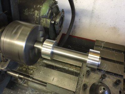
I'm pretty happy that my headstock is aligned to the bed - I probably get 2 thou (0.05mm) of taper over a 6" test bar supported only in the headstock. This was adjusted using the take a cut, adjust the appropriate foot height, take another cut method with a two collar test bar I made.

So to me the problem seems to be in the angle between the bed (in particular the bed surface opposite the carriage gib as that is what the carriage is pulled up against) and the cross slide dovetail (again in particular the surface opposite the gib). Uneven wear over the 60 some year life of the lathe have caused this the change (naturally all my facing is done at the headstock end of the bed where you would expect the most wear). From what I'm hearing here there is normally no adjustment of this angle. Only adjustment of the headstock to bed alignment is possible which doesn't change the fact that the cross slide is not at 90 deg to the bed, it would just allow you to even out the error between turning and facing.
For me turning a length true is more important than facing - if I'm facing an end where I know rocking (convexity) will be a problem a just cutout /recess the center a bit more to ensure a have an outer ring that is the contact surface. Looks like this will have to do until I fell up to a scraping challenge.
 
Last edited:
I'm not familiar with your lathe. Can you set the compound, if it has one, perpendicular to the work and face with it?

Tom
 
I'm not familiar with your lathe. Can you set the compound, if it has one, perpendicular to the work and face with it?

Tom

No, the top slide only rotates about 60 deg either side of parallel to the bed.

It is not a major issue to me, 98% of the stuff I face off is just to tidy up the end and get rid of the bandsaw marks so if it is slightly concave or convex is of no concern. When I know it will be a base or have to mate up well with something I recess the center a bit so it won't rock.

It was just a mater of I'm planning a bit of a 'mid life refurbishment' of the lathe as I have a few bits to replace (new belts, replacing a bull gear with a broken tooth, new bushes here and there, etc) so will be dismantling it and probably give it a clean/tidy up/ paint at the same time. I would of liked to correct this problem too if it could have been easily done.
 
Last edited:
Mikey
The quote I posted seems to agree with the recommendations in this book.

http://www.hobby-machinist.com/threads/connelly-on-machine-tool-reconditioning.41802/

Beginning on page 304 he describes the testing of a lathe for cross slide alignment with the axis of the headstock spindle.
But his procedure starts with assumption that the headstock is aligned with the bed and is not adjustable.

Thanks, that looks like the perfect reference. If I get a chance over the weekend I will tweak up the gibs and then recheck my level/diameter turning, lock the carriage and then try and quantify the cross slide using the chucked up parallel method described.
 
Ok did some experiments this afternoon. The lathe cuts a diameter true - better than expected actually only about 0.02mm of taper without any adjustment, so less than a thou of an inch. So spindle axis is parallel to the bed.
image.jpeg
Checked the cross slide as described in Connelly with a chucked up parallel and a dial gauge and it was all good. Should be cutting a bit concave if anything. ???? So the cross slide doesn't seem to be the problem.
Then I chuck up a bit of stock and faced it off, put a straight edge on it and it rocks - it's convex.
So I set the dial gauge up on the cross slide to measure the freshly faced surface and it has no movement at all from the outside to the center, but go past center to the opposite side and there is a slope away from the cross slide.
I think this means the chuck is the problem - that is the chuck jaw axis is at an angle to the spindle axis. Still trying to get my head around the geometry but I think that would lead to what I'm seeing - turning a diameter true but facing off to a point.
 
Pete,
I agree with you that the convex face sounds like the work piece axis is pointing away from the operator with respect to the ways. But, your pic shows the test piece in the chuck, and you say it only shows .02mm taper. Like you say, that doesn’t add up. If I may ask, how did you measure the taper?

Tom
 
I don't know.
Have you got a faceplate? Install it and take alight finishing cut on its face. Traverse the faceplate with a dial test indicator and test for concave or convex. This will take the chuck out of the picture.
 
Pete,
I agree with you that the convex face sounds like the work piece axis is pointing away from the operator with respect to the ways. But, your pic shows the test piece in the chuck, and you say it only shows .02mm taper. Like you say, that doesn’t add up. If I may ask, how did you measure the taper?

Tom

The picture is checking turning a diameter, take a light cut and measured the collars with a mic. All good. I have the test bar marked so it always goes into the chuck in approximately the same location.

I then just chucked up a short length of 40mm bar and faced it off. Turned out convex (or pointed)

My thinking is if the chuck was off it would be effectivly rotating the workpiece in a cone, with an increasing diameter the further you are from the headstock. But if you cut the diameter you would end up with the cut piece being cylindrical and no taper if the spindal axis is parallel to the bed - although with a 'bend' in relation to the piece inside the chuck.
It sort of makes sense as I previously marked the test bar to avoid having to take big cuts to bring it back into round if I put it back in the chuck in a different position.

Just having a hard time figuring out if that would result in a pointer face cut or not. My initial thought is not, I think you would just get a flat oval surface instead of a circular surface - but still flat.

The key I think is that the half of the face cut closest to the operator is parallel to the cross slide travel (no movement on the dial gauge), but when you measure the other half to the back of the lathe it is not.
 
Back
Top