Characterizing the G0709 quick change gearbox

mcdanlj

Registered
Registered
Joined
Aug 24, 2018
Messages
306
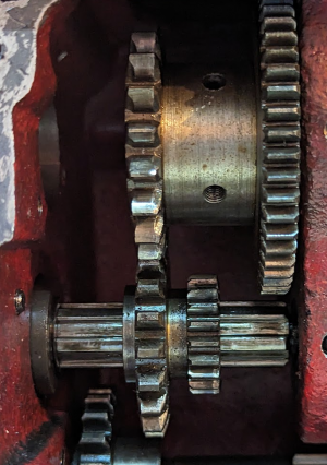
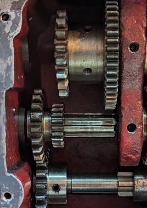
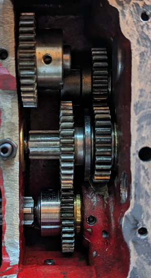
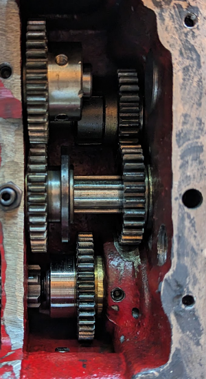
Since I had the gearbox open to clean it I decided to characterize it as completely as I can. I needed to do some of this to put it together correctly, and while I am about to convert to an electronic lead screw almost certainly driving this lathe for the rest of its life in ATW1 configuration (the maximum mechanical advantage, driving both the feed bar and lead screw), others might find this more useful.
Rotational domain definition​

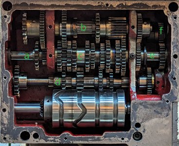
The manual doesn't have names for this, so I have to make something up. There are six independent axes of rotation in the gearbox. The gearbox is driven from the change gears on the left, and drives both the lead screw at the top right and the feed screw at the bottom left. I'll call these independent axes "rotational domains" and refer to them with lower-case letters a-f, since upper-case letters and numbers are both used for settings. They aren't labeled strictly in order, because different configurations drive them in different orders.


labeled.jpg

  • Zone a: Input from the change gears; terminates at the first divider
  • Zone b: The entire topmost axis, through both dividers
  • Zone c: Coaxial with zone a, but terminating on each side at the dividers
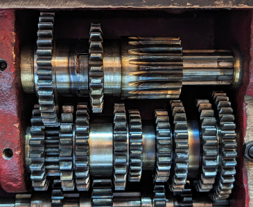
  • Zone d: Connected from wall to wall; holds a driving gear from a engaged only in the C configuration, a series of four gears that engage with 8 of the 10 gears in zone c selected by the 1-8 setting cam at the bottom, an output gear to the right of the rightmost divider, and finally directly drives the feed bar out the right side.
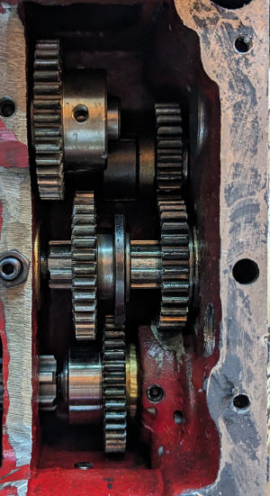
  • Zone e: Coaxial with zones a and c, has one sliding gear that couples b to f (Y configuration), leaves f uncoupled (X configuration; drives only feed bar not lead screw), or couples d to f (W configuration)
  • Zone f: The lead screw output

Driving Orders​

The A/B/C and W/X/Y selectors affect the order in which the domains are driven. I denote x driving y as xy here.
  • A/B: a→b→c →d
  • C...Y: a→d→c →b→e→f (used only for the lead screw; in these configurations the feed bar turns at the same rate relative to the input regardless of R/S/T or 1-8 settings)
  • W: d→e→f
  • X: Drives only the feed bar (direct from d) without engaging the lead screw at all)
  • Y: Used only with C to drive only the lead screw (b→e→f)

Driving Ratios​

The A/B/C, R/S/T, W/Y, and 1-8 selectors choose gear ratios. The direction in which those ratios apply from input to output depends on the driving order selectors previously described. I use the actual gear tooth counts here and do not reduce ratios to "proper fractions". This should help look up the gears in the manual and follow along.

A/B set the ratio of a:b
abdecimal
A20500.4
B19191.0

C sets the ratio of a:d
addecimal
C19220.8636

R/S/T set the ratio of b:c which is either unity (1:1 or 19:38 in one direction or the other):

bcdecimal
R38192.0
S23231.0
T19380.5

1-8 set the ratio of c:d

cddecimal
124330.7575
227330.8181
320220.9090
422221.0
523221.0454
624221.0909
726221.1818
828221.2727

W couples d:e 36:35 (1.0285) and e:f is permanently coupled 26:26 (unity)

Y couples b:e 35:35 (unity) and e:f is permanently coupled 26:26 (unity)
Configuration Close-ups​

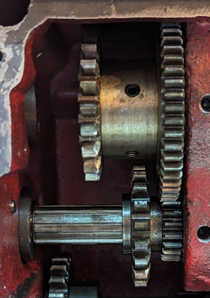
Here are pictures of the relevant section of the gearbox for each separate configuration option, with some description.

A/B/C Selector​

A​

Input a coupled to b domain 20:50
1689385754907.png

B​

Input a coupled to b domain 19:19
1689385831458.png

C​

Input a coupled to d domain 19:22
1689385855065.png

R/S/T Selector​

R​

Note that the 38:19 pair are always engaged with each other; in position R, a castellated pair couples the spline of axis b to the otherwise freely-rotating 38-tooth gear at the top left of this picture.
1689385968546.png

S​

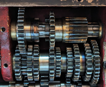
Here, the castellations are disengaged, leaving the 38-tooth gear as an idling gear driven by axis c, but coupling b:c at unity through a pair of 23-tooth gears.
1689386086487.png

T​

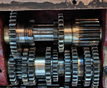
Here, the long 19-tooth gear at the right on axis b engages a 38-tooth gear on axis c.
1689386192841.png

W/X/Y Selector​

The W/X/Y selector determines which domain, if anym drives the lead screw.

W​

The d domain drives the lead screw
1689386373645.png

X​

The e domain is disengaged, and the lead screw is not driven
1689386419951.png

Y​

The b domain drives the lead screw
1689386470016.png


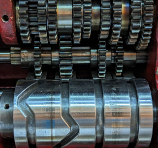
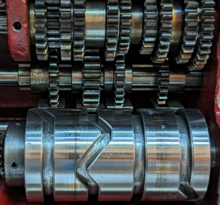
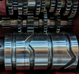
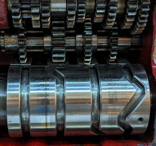
1-8 Selector​

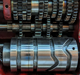
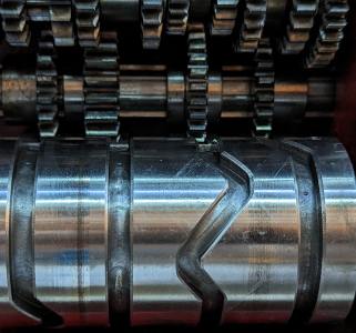
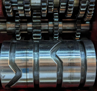
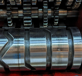
When reassembling the gear box, one of the trickiest bits is to make sure that the number selector is correct.

1​

24:33
1689386803094.png

2​

27:33
1689386891568.png

3​

20:22
1689386937247.png

4​

22:22
1689386963752.png

5​

23:22
1689387003020.png

6​

24:22
1689387044550.png

7​

26:22
1689387076300.png

8​

28:22
1689387114187.png


Worked Example​

ATW1 means (input) a→b 20:50 b→c 19:38 c→d 24:33 (feed bar) d→e 36:35 e→f 26:26 (lead screw)

20/50 * 19/38 * 24/33 = 9120/62700 = 456/3135 = 8/55 ~= .1454 (feed bar)

8/55 * 36/35 = 288/1925 ~= .1496 (lead screw)
 
Wow, talk about burning the midnight oil, excellent pictorial.
Felt like I was back in tradeschool.
Did you find anything you didn't like about the construction?
 
I'm not sure I know enough for an intelligent critique.

I wish the oil drain were actually at the low spot, and I wish the front seal gasket was a better design.

I wish it were easy to completely remove this and replace it with an ELS module instead of figuring out how to drive through it.

But mostly I was just learning. I didn't understand before how a single gear could mesh with two other gears that were coaxial with each other yet have different tooth counts; they do that by modifying the tooth form.

This was the document I wished existed when I first bought the lathe and was trying to understand the quick change gearbox as a black box.
 
Well, by the looks of it you're on the way. Given time you'll learn what you want in a machine.
Nothing wrong with being picky. It'll be to your benefit at the end of the day. Its good to start small.
 
Truly remarkable set of pictures, markings and descriptions. Amazing! I'm sure it will be helpful for others as well as you.

Figuring out how to do an ELS is interesting. Lots of legwork up front, but very gratifying to use. Pity to have the gearbox go fallow, but totally understand the motivation to go ELS. Mine has exceeded all my expectations. Good luck with your efforts, they will all be worthwhile.
 
I find it interesting to ponder: At what point in the past few years would it have become cheaper, if designing a new lathe, to provide an ELS instead of a quick change gearbox of this complexity? At least many of the gears in here are custom cut in various ways, and some clearly have some custom heat treatment. We have enough inexpensive hobby ELS projects to demonstrate that it would be substantially cheaper with a new design today. I doubt that would have been true ten years ago based just on servo prices. It's not clear to me where that crossover happened.

If I ever end up with a reason to remove the lead screw or feed bar from the lathe for maintenance, I'm likely to remove the gearbox, put it on my mill as an ersatz CMM (using the DRO and edge/center finding), and make an ELS housing to replace it. But I've gone a few months without a working lathe and I'm itching to make chips again, and that's too deep a rabbit hole for me today.
Very good point regarding taking advantage of modern tech. I'd love to have 27 tpi on my G0709, or be able to turn a knob on a whim to change the feed rate.

@hman (John Herrmann) pointed out "new tech" to me a few years ago regarding the broken speedometer/speed indicator on my DoAll 16" band saw. DoAll had a replacement for $1000; it's a run of the mill speedometer with a drive cable and magnetically coupled indicator needle. Mine was in pieces with a separated mainspring. I thought about trying to repair it; contemplated how to calibrate the mainspring for the magnetic coupling, etc.

John suggested a Hall-effect tach which cost around $15. The normal speedo reads in surface feet per minute instead of RPM's (wheel diameter doesn't matter; thing to control is the rate that the blade is moving through the material). John suggested putting 4 magnets on my wheel as a 16" diameter wheel has a circumference of 50.27" (pi x 16"). Four magnets on the wheel would fool the tach into seeing 4 "blips" every revolution. The math doesn't work out perfectly as 50.27" / 4 equals 12.57" instead of 12", but the error is less than 5%. It's a stinking band saw with a mechanical speedo giving SFPM; I suspect it's accuracy was maybe within 10% on its best day!

I really like the electronic display. Sure, not as "quaint" as a stock mechanical speedo, but no moving parts, no speedo cable pillow block to lube, etc. I'd be surprised if lathe manufacturers don't go to ETS at some point.

Bruce


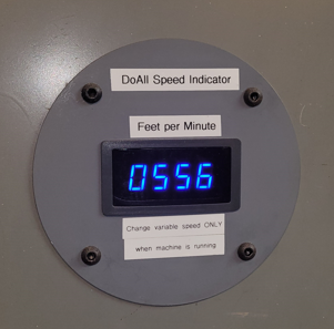
Digital speed readout
1689432816944.png
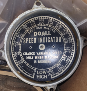
vs. the non-working speedometer
1689432842528.png
 
Last edited:
Similar to the four magnet trick, I wanted to know what SFPM I was getting on my belt grinder after I replaced the drive wheel with a smaller one. I realized that my 72" grinding belts were 6' long. I put 6 equally-spaced reflective stickers on the back of one belt and used an optical tach to read SFPM directly off those 6 reflective stickers.

The thing that sent me down the ELS road for my G0709 in the first place was thread-to-shoulder mode. But yeah, nearly arbitrary feeds and thread pitches is a nice bonus, with no mucking with change gears.
I've yet to get thread to a shoulder to work. Easy enough for imperial/imperial system. Metric is much harder to implement the re-syncing. Been thinking about how to do that on my ELS.

Do you have a VFD or braking system? That would make it much, much easier. I haven't figured out how to do that with my lathe. Darn lathe is against the wall and it's hard to access the VFD to play with it. If my shop were a little bigger, it would be child's play (quite the optimist :)) but at the moment, I have 10lbs of stuff in a 1lb bag!
 
I'm using clough42's ELS hardware and basing my firmware on on kwacker's branch, though with some additions of my own.

I don't have a VFD. I do have a foot brake, but with kwacker's approach you don't need or even use it. It just stops at the shoulder in the runout (or cutting the runout...) and you stop the spindle, back out the cross slide, reverse the lathe, reset the cross slide and advance the compound, then run the lathe forward again. (There's some button presses in there too.) It keeps the lead screw engaged the whole time, so it doesn't care what system you are cutting or which lead screw type you have.
 
Back
Top