
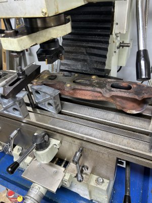
Hi all, I’m about to attempt to take the warpage out of a cast iron exhaust manifold for my 3.5 oboist truck. This will be the first time I have ever attempted this on my mill. Would love some input on feeds and spindle speeds. I will post a picture of my set up. Thanks in advance

-
Welcome back Guest! Did you know you can mentor other members here at H-M? If not, please check out our Relaunch of Hobby Machinist Mentoring Program!
You are using an out of date browser. It may not display this or other websites correctly.
You should upgrade or use an alternative browser.
You should upgrade or use an alternative browser.
Cast iron manifold
- Thread starter Pevehouse
- Start date
Hi all, I’m about to attempt to take the warpage out of a cast iron exhaust manifold for my 3.5 oboist truck. This will be the first time I have ever attempted this on my mill. Would love some input on feeds and spindle speeds. I will post a picture of my set up. Thanks in advance
Attachments
- Joined
- Apr 30, 2015
- Messages
- 11,333
Make sure the part is held securely- your setup looks shaky
I would use the bolt holes to fasten it and do it in several stages moving to different hole groups as you go
Lot of fixturing time but that's life
The other option of course is as mentioned above- use a belt sander and check frequently with a straightedge
I would use the bolt holes to fasten it and do it in several stages moving to different hole groups as you go
Lot of fixturing time but that's life
The other option of course is as mentioned above- use a belt sander and check frequently with a straightedge
Last edited:
- Joined
- Dec 9, 2021
- Messages
- 735
A local engine shop had a cylinder head grinder that was a cup wheel sticking up in a hole in a large flat surface. They moved the head around in a swirling pattern taking a tiny cut, then repeating until they had full contact. They used feeler gauges to monitor their progress and finished up with a straightedge and a light to get the last little bit. It took a bit of operator talent to get it to work well. Knowing where to start and where to go next was important, but once it was pretty flat it seemed like just moving around almost randomly got the job done.
- Joined
- Mar 26, 2014
- Messages
- 1,500
Most manifolds have a flat spot along one edge of the holes at 90 degrees to the face. You can put it face down first and mill these flat spots. You don't need much, maybe 10 -15 thou. This gives you a perpendicular surface to flip it over and clamp to an angle plate. Way more rigid when milling.
This is a video of the head from a Red Seal continental. I had a video of the manifold but it says it’s too big a file to load. This is on a horizontal but a vertical mill is the same principal
View attachment IMG_4023.mov
Martin W
This is a video of the head from a Red Seal continental. I had a video of the manifold but it says it’s too big a file to load. This is on a horizontal but a vertical mill is the same principal
View attachment IMG_4023.mov
Martin W
Last edited:
- Joined
- Mar 26, 2014
- Messages
- 1,500
This was my set up. Not much of a video. Lol
View attachment IMG_4012.mov
View attachment IMG_4012.mov
- Joined
- Jan 2, 2014
- Messages
- 8,853
I did mine here:
https://www.hobby-machinist.com/thr...eplacement-2012-dodge-ram.104127/post-1012222
Although most of that thread is about removing the old broken bolts, I do show some of my measuring, mounting to mill table and fly-cutting later in the thread:
https://www.hobby-machinist.com/thr...eplacement-2012-dodge-ram.104127/post-1012693
First I set it up on the surface plate with 1-2-3 blocks under the mounting ears. (I had to buy a couple more sets of blocks to have enough to support the manifold.) That allowed me to measure relative heights and then shim slightly for the least material removal. I then moved the entire thing keeping track of what shim went where to the mill table.
I used a high-speed steel (HSS) lathe tool bit as single point fly-cutter, so my feed and speed would be very different than yours.
For cutting cast iron with HSS I'd use around 80 sfpm cutting speed, but I see recommendations of 50-250 sfpm.
For cutting cast iron with carbide I see recommendations of 220-400 sfpm.
Brian