-
Welcome back Guest! Did you know you can mentor other members here at H-M? If not, please check out our Relaunch of Hobby Machinist Mentoring Program!
You are using an out of date browser. It may not display this or other websites correctly.
You should upgrade or use an alternative browser.
You should upgrade or use an alternative browser.
Bridgeport Riser
- Thread starter plongson
- Start date
I'm curious if you have any photos of the install, or at least your process. I have a 7" riser, spider and bolts setting on the floor next to my BP. I've seen videos of guys putting a 3/4" round in their spindle, and support that with a shade under 3/4" hole drilled in soft vise jaws. Set the table low (probably at least 9" from the top of travel), align the vise jaws with the 3/4" rod in the spindle and tighten down on the rod. Use an engine hoist (I have a gantry crane) to grab an I-bolt on the ram. Remove the four 1/2" bolts from the turret, and lift the head off the mill with the engine hoist and the knee. Once it's up and out of the way, swing the head from over the base at the turret for better access; the spindle will rotate freely. Install the riser/spider, swing the head back over the riser and reattach.
The concern I have with this process is that it seems that you could be side-loading the bearings in your spindle as I'd never be able to simultaneously raise the knee exactly with the gantry crane. I thought about sticking a 1/2" drive socket in the spindle collet, and sticking a wobble extension into that. Clamp the other end of the extension in the mill vise. That'd put a universal joint of sort right at the bottom of the spindle. That might be a bad thing if the head decides to tip to the side; something about 2 points not determining a plane.
Another option I've considered is making a wooden yoke that fits around the casting just above the spindle. Lag that into a couple of 4 x 6" that are clamped to the table. Then the load would be on the casting, not the spindle bearings.
I've had the riser for at least 5 years; one of these days I've got to pick a horse and get it installed!
Bruce
Sorry it took so long but I have a beam above the mill and used a come-along with an eye bolt in the mill. It wants to lean toward the heavy quill end and I used a ratchet strap around the front and around the chain. Sounds goofy but it worked great. Didn't use two spiders like some, just one spider on the bottom and long bolts. This is the way it was set up when I got the machine.
The bottom of the riser fit tight...like only .010 clearance so it has to go down STRAIGHT. Other than than that, pretty straight forward and BTW...I LOVE IT! no more hunch over...
Sorry no pictures
- Joined
- Nov 23, 2014
- Messages
- 2,606
Thanks for the ideas! Now you're all got me thinking which can be dangerous. . . The 4 x 4 idea seems to be stable, though as you noted, I'd tie everything together. Admittedly, I'm nervous about picking it up via two points over head; I'm anticipating it tipping to the side. My latest thought is to run a 1/2" threaded rod through the spindle to a wooden block at the bottom with a hogged out area so the load is on the casting, not the quill. I'd throw a piece of strap steel on top of the wood for a little more strength. At the top, drill a hole through a piece of bar stock for the top of the threaded rod. Then throw a couple of chains on the ends of the bar stock to give me (with the normal ram I-bolt) 3-points of lift. That should (?) be pretty stable.
Bruce
Bruce
- Joined
- Jul 29, 2014
- Messages
- 2,737
One somewhat unexpected complication was the new Bridgeport brand riser was slightly too big in diameter at the step to fit my Bridgeport clone mill, discovered in real time.  I had to take my 12" rotary table to a friend's mill and take maybe 0.050" off the riser internal diameter. I also had to make new bolts to fit the new length and metric threads on the spider. i used an engine hoist and several ratcheting straps to lift and keep the head level. i don't recall any particular problem doing this other than it was pretty close to the HF hoist height limit.
- Joined
- Jan 28, 2022
- Messages
- 829
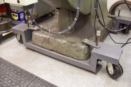
Good morning to all. My thoughts on spacers is they hamper smaller work where you need the spindle closer to the table. I do and have used my 4" riser one time in the last 25 years. When I did mount the spacer I realized I could not reach the switch so another mod. that made it a must was to lower the on/off switch and to further complicate the situation my mill is mounted on wheels that raised the mill another 3 1/2". Everything depends on the situation you're in to make the work possible. In my case I removed the spacer and life went on. The photo of the the switch was taken with the spacer removed but the switch relocation left lowered.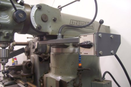


- Joined
- Apr 12, 2011
- Messages
- 3,472
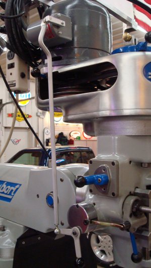
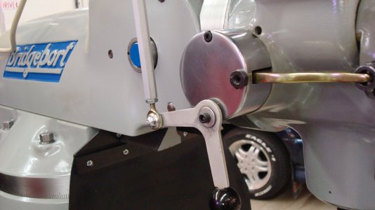
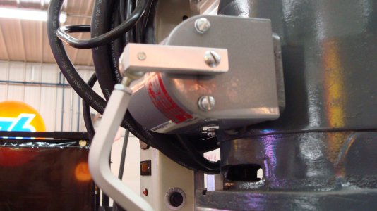
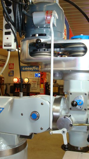
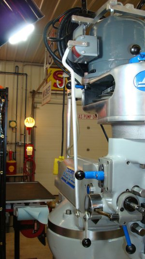
Kinda funny, you guys complaining you can't reach the power switch. I understand it, but the reach for the drawbar would my concern. I made this modification to the power switch because I found the location a bit inconvenient and unsafe. This was a conversion kit that the previous owner of the mill threw in when I bought it. Now mind you, I put my own spin on the end result. In fact, the only part from the original kit is the relocated handle and knob. This is a mod I highly recommend.


- Joined
- Jan 28, 2022
- Messages
- 829
Pristine Bridgeport, a work of art. A friend of mine has this set up that I do like. I did a mod. on his, at his request that added a travel limit for either rotation position and a reverse position lock out.Kinda funny, you guys complaining you can't reach the power switch. I understand it, but the reach for the drawbar would my concern. I made this modification to the power switch because I found the location a bit inconvenient and unsafe. This was a conversion kit that the previous owner of the mill threw in when I bought it. Now mind you, I put my own spin on the end result. In fact, the only part from the original kit is the relocated handle and knob. This is a mod I highly recommend.
View attachment 484736View attachment 484737View attachment 484738View attachment 484739View attachment 484740
- Joined
- Nov 23, 2014
- Messages
- 2,606
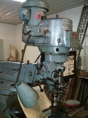
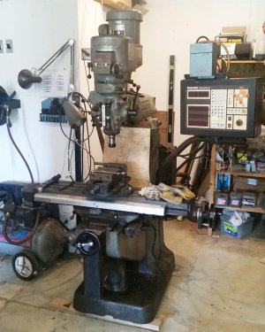
My BP has the lowered switch like Randy's; installed by the mill's previous owner. It's VERY convenient though in my case it doesn't serve as an ON/OFF switch, just spindle direction. The previous owner had wired it with a static phase converter which sets on top of the Anilam CNC control box. Yeah, looks cheesy at best with a DPDT wall switch (in the blue box above the Anilam). I was going to put a push button ON/OFF DPDT switch on it, but got used to flipping the wall switch. And continuing on my off-topic post, my static phase converter is powered by the DPDT switch; two feeds go to the switch and power the phase converter when the switch is thrown on. For whatever reason, if I turn the phase converter ON and throw the normal reversing switch to OFF, the phase converter buzzes. There are other posts here with the same experience. And I know, I loose 1/3 of the power using a static phase converter over a rotary. Being inherently lazy (or using the excuse, if it works, why change it), I figured a 2 HP motor generating 1 1/3 HP is okay. Especially when considering that a step-pulley BP has a 1 HP motor.
Bruce
Bruce


