Basic bolt force calculations. How would I do them?

Iron Filing

Registered
Registered
Joined
Feb 25, 2023
Messages
36
Hello,

Obligatory intro follows:
In asking this question I know I could go out, read several books, and eventually understand how to do this; but I'm working on project so I needed deal with this sooner rather than later. I'll happily read those books at a later date. I also searched online, but the websites I found don't agree with each other on the math and even admit that they're over simplifying the matter. Likewise, I could buy Solidworks, or something, but I'd rather learn the trade than learn the app.


I'm trying to create a fixture to hold parts down. They are between ~10 and ~20 square mm in size and almost perfect rectangles. I'm uncertain whether I should be using M6 or M8 bolts or maybe something else, like my head ;) . I don't even know if my fixture can withstand the force I wish to place on it, which would be 40in-lbs of tightening force on each of the 2 bolts.

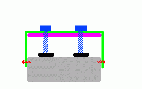
I've attached a picture of the setup. The silver part is the base. It's made of aluminum and is almost exactly 40mm x 20mm. I can't change anything on the base at all for any reason. It takes two M3 1mm pitch screws that penetrate 8mm deep into the base on each side (4 total) (They're considered coarse threads normally used for wood). I'm planning on using a piece of scrap stainless for the green part to wrap around the base. I think it will be about 1-2mm thick, I have to look. The black things are the parts, of course. The blue screws I think will be M6 1mm pitch (which is considered fine pitch). The purple part is a piece of scrap steel used for giving the bolts something to grip to and is 3.4mm in thickness.

Feel free to give me formulas instead of just doing the work for me. I'm not trying to be lazy, I just don't know how to do this.

How do I calculate if the rig can withstand 40in-lbs of torque on each of those blue bolts?
How much force would be applied to each part exactly? I know how to do PSI and convert mm->inches, but there has to be some loss when tightening a screw.
Does the purple plate have enough depth to allow an M6 bolt to grip properly? I have no idea how deep a nut should be.
Should I be using a larger bolt than M6? I could go as high as M10.

Thanks!
 

Attachments

  • fixture.gif
    fixture.gif
    3.6 KB · Views: 7
This seems a little like a homework problem... Not that it is, but some things don't make sense.
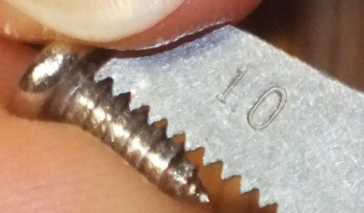
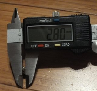
M3 screws have 0.5mm pitch. 0.5mm is considered the standard coarse pitch. Not sure that I've seen 1mm pitch on M3. A 1mm pitch on a 3mm screw would make for an exceedingly weak screw, as the root of the screw would only be roughly 1.27mm.
M6 screws are 1mm pitch, and are considered standard coarse threads, not fine.
One really only needs three threads to hold a screw, so using 3.4 mm ought to be ok. How to calculate the rest of the forces, I don't know. Somehow I think stuff could bend, buckle or simply shear, but I'm not a mechanical designer. Good luck.
 
You're finding mixed and oversimplified answers, because you're looking for a quick answer to a subject that takes a college degree to sort out well.

I've got to say that I'm lost as to what you're trying to do here. I see two screws pushing downwards on the base, pulling upwards on the purple piece, and being restrained by the green piece? So then the red squiggles are where you're trying to decide if it's M6 or M8? If that's the case, a couple of M6 screws in shear (not even tightened properly) will gladly hold back the four wood screws at 40 inch pounds.

Finding a torque/tension value outside of "standard torque", which is what shows on most available torque tables is less about looking up values, and more about experimentation. Torque is such a bad way to measure how tight a fastener is, it's not even funny. You're right, there is friction, and in fact, in the end, it is very nearly ALL friction. The lead of the threads, the theoretical inclined plane.... That stuff goes out the window, as the percent is so low that any error throws you off so far it's not even worth doing the math.

How much oil, cutting oil, coolant, or other contaminants is going to get on these, and how consistant will that be? That could double a force calculation result on a screw like your wood screws. What about the finish? The torque/tension is going to change tremendously if you use this enough to start wearing on the finish of whatever screw you're using. Oxide, plating, whatever...

Why is the 40 inch pounds fixed? If you could loosen that spec, you could use just about any fastener you wanted.
 
This seems a little like a homework problem... Not that it is, but some things don't make sense.
M3 screws have 0.5mm pitch. 0.5mm is considered the standard coarse pitch. Not sure that I've seen 1mm pitch on M3. A 1mm pitch on a 3mm screw would make for an exceedingly weak screw, as the root of the screw would only be roughly 1.27mm.
Ugh, now I have to take pictures for you. ;)
Please bear in mind that the images were not taken from a perfect vertical.
DSCF4434.jpg
DSCF4428a.jpg

IIRC, I did try other pitches, including SAE, but 1mm was all that would fit.


M6 screws are 1mm pitch, and are considered standard coarse threads, not fine.
I recalled incorrectly. Thanks for pointing it out.

You're finding mixed and oversimplified answers, because you're looking for a quick answer to a subject that takes a college degree to sort out well.

I've got to say that I'm lost as to what you're trying to do here. I see two screws pushing downwards on the base, pulling upwards on the purple piece, and being restrained by the green piece? So then the red squiggles are where you're trying to decide if it's M6 or M8? If that's the case, a couple of M6 screws in shear (not even tightened properly) will gladly hold back the four wood screws at 40 inch pounds.
I tried to point out that the red squiggles are the M3 screws. There are 4 total, 2 on each side.

Finding a torque/tension value outside of "standard torque", which is what shows on most available torque tables is less about looking up values, and more about experimentation. Torque is such a bad way to measure how tight a fastener is, it's not even funny. You're right, there is friction, and in fact, in the end, it is very nearly ALL friction. The lead of the threads, the theoretical inclined plane.... That stuff goes out the window, as the percent is so low that any error throws you off so far it's not even worth doing the math.
That's unfortunate. I thought for sure I could be the "good scientist" and actually categorize how much force is being applied to the parts instead of leaving that as an unknown once the correct value has been determined by experimentation... Maybe a Wheatstone bridge sensor would work...
Let me ask you this then, what is the relationship between the amount of force applied to a part at, say 10 in-lbs vs. say 20 in-lbs? Is it linear, or is the force ratio curve logarithmic, or what?

How much oil, cutting oil, coolant, or other contaminants is going to get on these, and how consistent will that be? That could double a force calculation result on a screw like your wood screws. What about the finish?
I wasn't planning on greasing anything to remove that variable from the equation. The screws are 304 stainless steel.

The torque/tension is going to change tremendously if you use this enough to start wearing on the finish of whatever screw you're using. Oxide, plating, whatever...

Why is the 40 inch pounds fixed? If you could loosen that spec, you could use just about any fastener you wanted.
I could loosen that spec. In fact, I expect to do so. I'm just not certain what sort of force would be necessary so I decided to prepare the fixture for the worst case scenario. The actual force will have to be determined after experimenting and I had hoped to calculate how much I was applying by extrapolating from the amount of force I was using to screw down the M6 bolts.

Thanks again!
 
The torque applied to an M6-1 steel machine screw is expected to be 3.4 N-m, or less,
and with a pitch of 1 mm, the force angle for axial force calculation is arctan( 1/(pi*(6-1)) ) = 3.6 degrees
(the 'average' diameter being a millimeter less than nominal, because that's where the sidewall of the thread
has its helical centerline).

Torque ratings are tabulated for steel fasteners of various types; one needs that info to tighten 'em right.

So, with lubrication, typical axial force of the screw is 3.4 N-M * (0.0025 M) / tan(3.6 degrees) = 0.135 newtons
A newton is 4.46 pounds, so I wouldn't expect that amount of force to shear an M3 wood screw.

There's high-strength steels (most cap screws are graded lots higher than common fasteners)
that take higher torques, of course.
 
I tried to point out that the red squiggles are the M3 screws. There are 4 total, 2 on each side.

Gotcha. I guess I got that turned around.

The good news is that you won't have to mess with toque or tension on those wood screws. You've got a very good estimate of the "root diameter", (can you call it that on these?), and with those being in shear, if you know what the screws are made of... You can get a pretty accurate minimum shear value for that, and decide what percentage of that you want to utilize. My gut says you'll be using shear on those, as you won't develop the clamp load to pinch it in place.

That's unfortunate. I thought for sure I could be the "good scientist" and actually categorize how much force is being applied to the parts instead of leaving that as an unknown once the correct value has been determined by experimentation... Maybe a Wheatstone bridge sensor would work...

That's typically how it would be done at the design/prototype level. Some sort of a load cell for smaller stuff like this. Often hydraulic for larger things. There's so many variables that making (or having made) custom tooling is cheaper than figuring it out, and still having to have some way to measure end result anyhow.

Let me ask you this then, what is the relationship between the amount of force applied to a part at, say 10 in-lbs vs. say 20 in-lbs? Is it linear, or is the force ratio curve logarithmic, or what?

That's a good question. I've never seen that laid out. having seen a few particular application charts, I'd GUESS that closer follows a geometric progression than a logarithmic one. But I suspect if it had a simple (relatively simple) mathematic relationship, it would probably be common knowledge by now. Or at least in the stuff you could look up. But I've never come across such. That doesn't mean it doesn't exist, I've just never come across it.

I wasn't planning on greasing anything to remove that variable from the equation. The screws are 304 stainless steel.

That's probably a good and a bed thing. 304 bolts (cap screws...) won't be plated, which means that as long as you're staying well under "standard torque" values, once you burnish the threads in the bolt and the hole, it should stay a lot more consistent over time. The bad news is that makes the friction part of the equation higher, and the clamping part lower, which affects accuracy greatly. Of course any lubrication it gets, including cutting or cooling fluids are going to change that value, but if you have control over that, either by eliminating lubrication, or keeping it consistent, then you've eliminated a huge variable.

I could loosen that spec. In fact, I expect to do so. I'm just not certain what sort of force would be necessary so I decided to prepare the fixture for the worst case scenario. The actual force will have to be determined after experimenting and I had hoped to calculate how much I was applying by extrapolating from the amount of force I was using to screw down the M6 bolts.

Do you have any rough idea of what the final force is going to be?

How do you plan to determine the necessary force? Simple experimentation?

If it is going to come down to experimentation, see if this fits- The only place you'll interact with this fixture is at the bolt head, when you tighten it, right? So does the actual force actually matter? A new fixture and a new bolt, run tight (ish) and loosened a dozen times, would simply documenting the torque and the results accomplish the same goal as documenting the theoretical pressure and the results?
 
The torque applied to an M6-1 steel machine screw is expected to be 3.4 N-m, or less,
and with a pitch of 1 mm, the force angle for axial force calculation is arctan( 1/(pi*(6-1)) ) = 3.6 degrees
(the 'average' diameter being a millimeter less than nominal, because that's where the sidewall of the thread
has its helical centerline).
Forgive my ignorance, what does that calculation tell me?

The good news is that you won't have to mess with toque or tension on those wood screws. You've got a very good estimate of the "root diameter", (can you call it that on these?), and with those being in shear, if you know what the screws are made of... You can get a pretty accurate minimum shear value for that, and decide what percentage of that you want to utilize. My gut says you'll be using shear on those, as you won't develop the clamp load to pinch it in place.
Thanks

That's typically how it would be done at the design/prototype level. Some sort of a load cell for smaller stuff like this. Often hydraulic for larger things. There's so many variables that making (or having made) custom tooling is cheaper than figuring it out, and still having to have some way to measure end result anyhow.

That's a good question. I've never seen that laid out. having seen a few particular application charts, I'd GUESS that closer follows a geometric progression than a logarithmic one. But I suspect if it had a simple (relatively simple) mathematical relationship, it would probably be common knowledge by now. Or at least in the stuff you could look up. But I've never come across such. That doesn't mean it doesn't exist, I've just never come across it.

That's probably a good and a bad thing. 304 bolts (cap screws...) won't be plated, which means that as long as you're staying well under "standard torque" values, once you burnish the threads in the bolt and the hole, it should stay a lot more consistent over time. The bad news is that makes the friction part of the equation higher, and the clamping part lower, which affects accuracy greatly. Of course any lubrication it gets, including cutting or cooling fluids are going to change that value, but if you have control over that, either by eliminating lubrication, or keeping it consistent, then you've eliminated a huge variable.
:)

Do you have any rough idea of what the final force is going to be?
I don't think it would exceed 20inlbs, but that's really just a worst case guess. I decided to take my worst estimate and multiply it by 2. It seemed a good idea.

How do you plan to determine the necessary force? Simple experimentation?
In this case, yes. If I had some really expensive equipment I could take some really careful measurements of the parts and calculate exactly how much force I needed.

If it is going to come down to experimentation, see if this fits- The only place you'll interact with this fixture is at the bolt head, when you tighten it, right? So does the actual force actually matter? A new fixture and a new bolt, run tight (ish) and loosened a dozen times, would simply documenting the torque and the results accomplish the same goal as documenting the theoretical pressure and the results?
Provided that I could place whatever is measuring the torque between the parts and the bolt (black and blue parts). I just wasn't sure what type of a strain gauge to buy -- and they're one application only and aren't particularly cheap. So I thought I'd be better off using my head.

Thanks!
 
The torque applied to an M6-1 steel machine screw is expected to be 3.4 N-m, or less,
and with a pitch of 1 mm, the force angle for axial force calculation is arctan( 1/(pi*(6-1)) ) = 3.6 degrees
(the 'average' diameter being a millimeter less than nominal, because that's where the sidewall of the thread
has its helical centerline).
Forgive my ignorance, what does that calculation tell me?

You can control the hold down force with a torque screwdriver, torque wrench, or even just
the settings on an electric screwdriver, up to some reasonable limit. There's tables of
these limits, for common fasteners, and you can look up that torque for M6. From there,
the pitch angle of the screw thread can tell you how much downward force results from
tightening. That '1mm' pitch implies that a full circumference of the screw is traveled
along that curved ramp to make a 1mm distance traveled, and that makes the
connection between torque and screw-applied force on the object being clamped.

The rest of it, is just geometry.

This all boils down to torque-times-radius equals force-times-distance equals work
as a general rule for screws.
 
Back
Top