- Joined
- Jan 1, 2014
- Messages
- 233
Z backlash can be annoying on fine drilling, boring and milling operations and it because of the pinion/rack design of the quill mechanism. There is a reason these little mills are cheap but it doesn't mean they cannot be improved. I found that to get a few thou change it could be problematic if you didn't have the backlash "taken up" correctly with the control handle, the result being that the quill could drop the amount of the backlash when you released the quill lock. The only way I could see to correct this deficiency was to have the return spring acting directly on the quill rather than on the pinion.
I did a lot of measuring and figured that a "windlass" arrangement could be fitted within the head casting to do the job. Moving the pinion spring case to the new "windlass" could provide the same return action as long as I replicated the same "leverage" power that the geared pinion and spring had on the quill. On my machine the pinion rotates 1 2/3 turn for 5.625" of quill travel. Dividing the travel by the turns gives you 3.376. Dividing this again by Pi give you 1.074. Thus a 1" dia windlass with a 1/8" return cable wrapped around it (effective dia of 1 1/8") would experience 1.591 revolutions during full quill travel. This is close enough to the original 1.6 pinion revs to give the return spring, when transferred to the windlass shaft, the same mechanical advantage over the quill as in the original configuration.
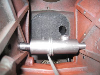
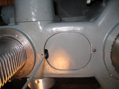
The top picture shows the windlass in place. The thru shaft is anchored to the windlass by the screw on the left. Yes, there is enough room to come up from the bottom with a long allen key to run the screw into place. The location of the shaft fore/aft was determined by the need for the cable to just miss the casting when exiting the bottom of the head as in picture two. The cover plate had to be slightly modified. Vertical location was simply a matter of where it looked good and for the shaft to miss the internal casting ribs as in picture one. "Squareness" of the shaft in X,Y and Z was a matter of measuring back from the original pinion shaft holes in the head over to the desired location.
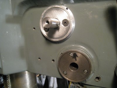
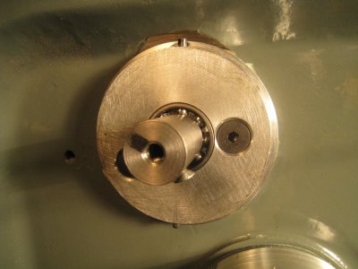
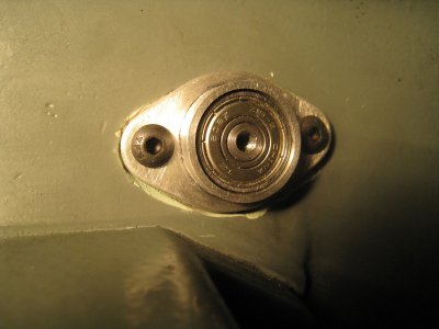
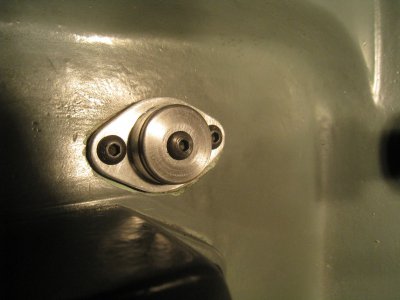
A spring cap carrier was turned up out of AL exactly the same as the original and mounted on the head in the desired place. Later it was fitted with a ball bearing. A small ball bearing was mounted on the right side against a shoulder on the shaft and with a suitable end cover cap to hold it in place. The shaft is now "captured" between the bearings.
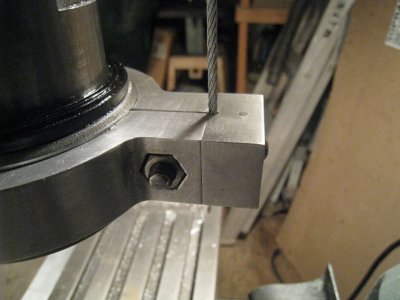
A block was added to the back of the quill clamp to anchor the return cable.
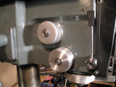
This shows the spring (and cover) mounted to the end of the windlass shaft and a new "false" cover, turned up on the lathe, to finish off the pinion shaft again.
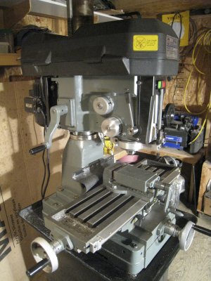
This shows the finished setup. Someone curious might ask about the "second" cover, but it fits in with the general aesthetics of the mill. It will look better painted which will happen when I am all finished tinkering.
Finally, the quill is now always subjected to a direct upward pull equal to the spring tension, and, as such, eliminates any "backlash" concerns. Also, other than a lot of fiddling and planning, the only cost involved was for the bearings and a bit of cable, about $5 total, the rest came out of the scrap bin.
Hope someone finds this interesting.
Comment are welcome


I did a lot of measuring and figured that a "windlass" arrangement could be fitted within the head casting to do the job. Moving the pinion spring case to the new "windlass" could provide the same return action as long as I replicated the same "leverage" power that the geared pinion and spring had on the quill. On my machine the pinion rotates 1 2/3 turn for 5.625" of quill travel. Dividing the travel by the turns gives you 3.376. Dividing this again by Pi give you 1.074. Thus a 1" dia windlass with a 1/8" return cable wrapped around it (effective dia of 1 1/8") would experience 1.591 revolutions during full quill travel. This is close enough to the original 1.6 pinion revs to give the return spring, when transferred to the windlass shaft, the same mechanical advantage over the quill as in the original configuration.


The top picture shows the windlass in place. The thru shaft is anchored to the windlass by the screw on the left. Yes, there is enough room to come up from the bottom with a long allen key to run the screw into place. The location of the shaft fore/aft was determined by the need for the cable to just miss the casting when exiting the bottom of the head as in picture two. The cover plate had to be slightly modified. Vertical location was simply a matter of where it looked good and for the shaft to miss the internal casting ribs as in picture one. "Squareness" of the shaft in X,Y and Z was a matter of measuring back from the original pinion shaft holes in the head over to the desired location.


A spring cap carrier was turned up out of AL exactly the same as the original and mounted on the head in the desired place. Later it was fitted with a ball bearing. A small ball bearing was mounted on the right side against a shoulder on the shaft and with a suitable end cover cap to hold it in place. The shaft is now "captured" between the bearings.

A block was added to the back of the quill clamp to anchor the return cable.

This shows the spring (and cover) mounted to the end of the windlass shaft and a new "false" cover, turned up on the lathe, to finish off the pinion shaft again.

This shows the finished setup. Someone curious might ask about the "second" cover, but it fits in with the general aesthetics of the mill. It will look better painted which will happen when I am all finished tinkering.
Finally, the quill is now always subjected to a direct upward pull equal to the spring tension, and, as such, eliminates any "backlash" concerns. Also, other than a lot of fiddling and planning, the only cost involved was for the bearings and a bit of cable, about $5 total, the rest came out of the scrap bin.
Hope someone finds this interesting.
Comment are welcome


