Arduino Based Tool Sensor plate.

You might want to take a look at this for some ideas.
Thanks for the link!
I did see that one while checking around on the web, But I think I may have come up with a even easier option?
Now to see how long it takes for the parts I ordered take to get here!

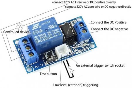
I found a relay that has a 5VDC in-put control voltage & it will handle the 24VDC gearmotor's voltage.
5VDC Relay 2.jpg
The relay also has a separate low level trigger connection which will make it easy to hook up a touch plate that will act as a switch that controls the relay.
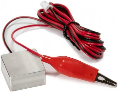
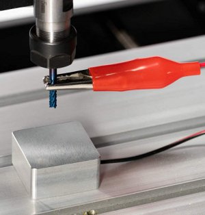
Touch Plate 1.jpgTouch Plate 3.jpg

Doug
 
doesn't even need an Arduino.
I plan to try it with out the Arduino at first just to see how everything works out.

If I find that I need a quicker response time to prevent over traveling or relay delay, I can always try connecting the relay up with the Arduino & the KY-036 sensor.

Doug
 
Last edited:
A good trick on the touch.probes is to stick a magnet in the clip jaws. Then you can just.stick it to the spindle.

Sent from my SM-G892A using Tapatalk
 
A good trick on the touch.probes is to stick a magnet in the clip jaws. Then you can just.stick it to the spindle.
Good tip, Thanks!

I seen several touch plate set-ups on e-bay that used a magnetic coupler for the spindle like the one shown in post #5, But they run around $100.
The one I got off of Amazon was $12.

Doug
 
I use DC motors a lot and normally I allways turn off the DC and put a short on the motor to stop it nearly instantley via a relay or a fet or a DC ssr

Gary
 
Here's an update on my search for a Arduino based tool bit touch plate!

I did try out the relay shown in post #11 & it actually worked pretty good.
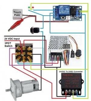
Here's a drawing of how it was wired up.
Zero Touch Plate Wiring 5VDC 1.jpg
Being I haven't finished the router lift yet I didn't have a way to actually test it with the motorized lift & the router bit.

Doug
 
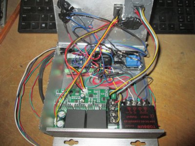
Thinking about a little more & finding some more information on the Arduino's & the set-up process, I decided to go ahead & try it out with a Arduino Nano (clone) just to see how much it would make a difference. Having the adjustable sensitivity trim pot does help dial it in a little better.
IMG_7607.JPGIMG_7594.JPG
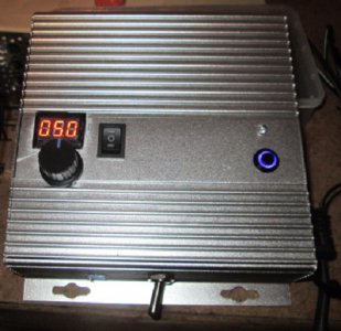
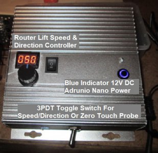
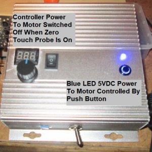
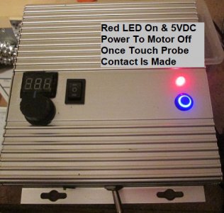
Here's a little more information on how the controls work.
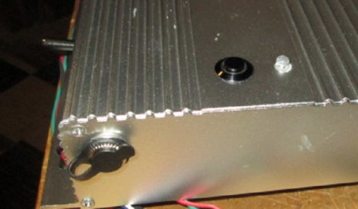
Control Box 1.jpgControl Box 2.jpgControl Box 3.jpg
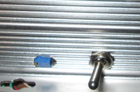
With the lower toggle switch in the left-hand position it allows speed & direction control of the router lift motor.
With the lower toggle switch in the right-hand position it provides 5VDC power to the motor that is controlled by the momentary push-button, Once the router bit with a alligator clip lead touches the touch plate the power to the motor is switched off through the Arduino & relay.

Doug
 
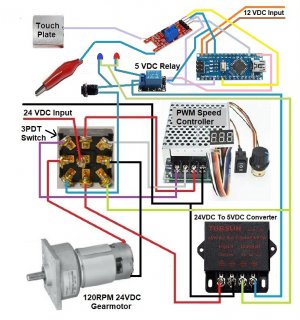
Here's a drawing showing how it's basically wired up.
Zero Touch Plate Wiring 5VDC NANO 1.jpg
The sensor I used was a REED SWITCH MODULE that I modified to work with the touch probe leads.
On the bottom of the control box I have access to the trim/pot for adjusting the sensitivity.
Control Box 4.jpg

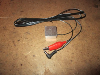
On the right side of the control box I have a small power plug that's used to connect the touch probe leads.
Control Box 5.jpgDIY Touch Plate.JPG

Doug
 
I've seen a lot of 3D printers that solve the problem of overshoot by taking two readings: one faster to get there, then back off a little and go in very slow.
 
I've seen a lot of 3D printers that solve the problem of overshoot by taking two readings: one faster to get there, then back off a little and go in very slow.
Yeah, I use to run an old Bridgeport EZ-Trak & it had a system like that.
This is just a simple manual touch sensor probe, no external computer controlling it.
The Arduino based relay set-up basically acts as a sensitive fast acting switch that turns off the power to the motor.

The router table for this project is currently on hold until it warms up here in Michigan. From my temporary set-up tests, it should be more than accurate enough for a router table set-up.

Doug
 
Back
Top