Arduino based Tachometer

arlo

Active User
Registered
Joined
Nov 15, 2012
Messages
56
I built a simple tachometer using a Hall Effect magnetic sensor and an arduino (AVR) microcontroller. This project is easy enough for a beginner with one important caveat. The caveat is that you have to have some knowledge of the arduino and its programming. If you have an interest in microcontrollers, there are a lot of options for the beginner. The support I've gotten from the arduino community has been outstanding.

I wanted to measure the rotational speeds of my mills and drill press. All three of my machines have at least two speeds determined by pulley selection. I thought the best approach would be one that would allow to rapidly measure the possible combinations and let me build a table of speeds for each machine. I did not want a permanent tachometer attachment.

In looking on line, I found that the most common approach is stroboscopic. After I'd nearly finished this project, I found that there are simple and cheap stroboscope based devices available. Maybe I could have used one of them but I am happy with what I built.
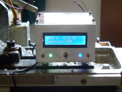

inUse.JPG

If anybody is interested, I've attached an OpenOffice presentation that documents what I did. If OpenOffice doesn't work for you, I can try a different format. Also attached is the arduino code.

inUse.JPG
 

Attachments

  • Tach.zip
    386.2 KB · Views: 96
Holy crap Arlo! That is wicked cool!

I have a beginners Arduino kit which I plan to experiment with when I am finished moving in my shop, a few weeks from now. So I am familiar with the open source sharing, but have not done a stitch of programming yet.

So I think your project is so cool! I did a bit of Fortran and C+ in engineering college years ago, if I can remember any. How easy was it to become efficient enough in the Arduino code to really use it well?

Btw, by TOTAL luck, I found a Monarch Pocket Tach 100 (optical) on Craigslist for $25 two weeks ago! But I appreciate your post, and will certainly download your code you attached to my laptop when I'm home.

Bernie
 
Re: Arduino based Tachometer ++

Add me to the list of people who plan on playing with this stuff...
 
For those of you interested in digital tachometer algorithms you might want to look at Microcomputer Based Wide Range Digital Tachometer. It does a fairly decent job of explaining the pros and cons of several of the most common algorithms as they relate to the width of the RPM range it can measure.

Note that it is not the only document on the subject but I found it to be the easiest one to understand.

Arvid
 
Last edited:
Arduino programming is very straight forward and moderately easy. Once you have all of the components you cann get to the "hello world" point rather quickly. Arduino is a step up from Picaxe and a step down from true PIC programming in C or C++. Arduino also has a huge, well supported library of proven snips of code that will ease the entry into that labguage considerably. There are also several different flavors of the system available such as Uno, and Duemenlove among others. Ther are a multitude of ready made shields and BOB (Breakout Boards) that are a simple wire it in and go proposition too. I started with Picaxe, did Arduino, and have moved on to working with the 16f877A family using c and a compiler to flash the memory and load my programming. For my Three tier Beer Sculpture I am planning to use a 40 pin Picaxe to monitor temps and make logic decisions for the system. It uses Basic programing language and also has a lot of snips available so I dont have to write every bit of the code for my application. Hope this enlightens any one who may be interested in using or learning to program micro controllers or create embedded projects.

Bob
 
Thanks Bob and thanks Arvid! I have got to get back to my laptop and download these!
 
For those of you interested in digital tachometer algorithms you might want to look at Microcomputer Based Wide Range Digital Tachometer. It does a fairly decent job of explaining the pros and cons of several of the most common algorithms as they relate to the width of the RPM range it can measure.

Note that it is not the only document on the subject but I found it to be the easiest one to understand.

Arvid

Thanks for the link to that paper. I'm not smart enough to understand it on the first reading but I'll spend some more time on it. One thing I should mention is that most of the tachs I've read about basically count the number of revolutions in a set period of time (in the paper, they call it the "Method of Constant Elapsed Time"). They mention some of the pros and cons of this method but I think the biggest problem is that for relatively low rpms and short measurement times, the CTE method has errors by inconsistently counting incomplete revolutions during the measurement period. I tried to get around this problem by using a constant number of pulses and using time as the dependent variable. For instance, I use the microcontroller's very accurate internal clock and get the start time. I count some constant number of pulses. When I reach the threshold pulse, I read the accurate time again. When I started playing with this, I arbitrarily picked 100 pulses because I thought I'd need that many for accuracy. So a 600 rpm would require 6 seconds of measurement time. As I experimented with fewer pulses, I found that I was getting almost the same result for as few as 20 pulses. I was surprised that my measurements with 20 pulses were within less than 1% error from the Nova's. I could find a lab grade stroboscope and figure out which was closer to the truth but for my purposes +/-5%v is probably overkill.


For anybody looking for a gateway into really fun electronics, microcontrollers are great. Bob notes that there are good choices besides the arduino. Go to the arduino.cc forums and read about the neat projects people are building. I've been too lazy to learn more than one system but I hope my Raspberry Pi gets delivered tomorrow. If you haven't read about it and you're interested in electronics/low level computing, take a look at it.
 
One thing I should mention is that most of the tachs I've read about basically count the number of revolutions in a set period of time (in the paper, they call it the "Method of Constant Elapsed Time").

I believe that is the 'Counting Measurement Method', not the "Constant Elapsed Time" method. The number of encoder pulses are measured during a fixed time period, appropriate math is applied, result is displayed.

They mention some of the pros and cons of this method but I think the biggest problem is that for relatively low rpms and short measurement times, the CTE method has errors by inconsistently counting incomplete revolutions during the measurement period.

If you change 'the CTE method' to 'the CMM method' then your assessment is correct for low RPM and\or low resolution encoders.

I tried to get around this problem by using a constant number of pulses and using time as the dependent variable. For instance, I use the microcontroller's very accurate internal clock and get the start time. I count some constant number of pulses. When I reach the threshold pulse, I read the accurate time again.

This sounds like a variation of the "reciprocal measurement method" where the encoder pulse width is measured. The fact that you are measuring the pulse width of 1, 10, 20 or 100 pulses does not make any difference. RMM suffers from issues at high RPM and\or high resolution encoders, but counting the time for multiple pulses rather than one may mitigate some but not all of that issue at the expense of display refresh rate.

When I started playing with this, I arbitrarily picked 100 pulses because I thought I'd need that many for accuracy. So a 600 rpm would require 6 seconds of measurement time. As I experimented with fewer pulses, I found that I was getting almost the same result for as few as 20 pulses. I was surprised that my measurements with 20 pulses were within less than 1% error from the Nova's.

This makes sense as you are using a pretty straight forward RMM method and simply varying the 'pulse width' by modifying the number of pulses counted. Assuming you would not run into internal timer resolution issues you could go as low as one pulse and get very near the same [reasonable] results and accuracy.

The "constant elapsed time" or CET method attempts to resolve the issues by counting both the number of pulses ... the CMM method ... and the width of an encoder pulse ... the RMM method ... and both values are used in a way such that the 'better' value is used. As such the tachometer exhibits a much wider bandwidth than either method would provide by itself.

From what you have stated I do not think you are not using the CET method because you counting of the number of pulses does not enter into the algorithm other than to determine the 'pseudo pulse width'.

But no mater what you, have a working tachometer and that is all that mattered.

Congratulations and nice work.

Arvid
 
I also had surfed around and tried a few different ways to do this. I tried optical sensors and various hall effect sensors. Hall effect seems to work the best as a sensor. Of all of the software variations I have tried, this looks the simplest and best for RPM rates. Having all of the parts hanging around, I will give this a try on the bench. I want to add PWM for the DC speed control voltage on my lathe to get a constant speed control using the tach for feedback.

Anyway thanks for the inspiration.
 
Actual code for several of the methods described below are found here.

My problem at the moment relates to the sensor, using a frequency generator all is fine. i am using a TCRT5000 with a 2N3904 booster into a schmitt trigger. For the reflective sensors, the distance/gap is important. If too close or too far the signal strength reduces considerably. I had used resistor values found somewhere on the www, but it turns out they are wrong. So back to basics today, recalculated the values from datasheet. Next is to redo the tiny board.

BTW if you want to solidly mount something on metal without drilling holes, e.g. to test out a location for the sensor, use Plumbers Goop. It is silicone based but dries semi hard. Very solid mounting. I use this on my Unmat since I don't want to turn it into Swiss cheese mounting my additions.

Gerrit
 
Back
Top