Anybody ever heard of "Unique 3 Phase"?

Barncat

H-M Supporter - Gold Member
H-M Supporter Gold Member
Joined
May 14, 2018
Messages
335
It is a book that purportedly shows how to get three phase power from a single phase source using transformers and capacitors. It sounds like it is similar to running a 3 phase welder on single phase using the haas-kemp method. Was wondering if anyone has done this?
 
The only phase shifts I have seen in transformers involving 3-phase transformers is the 30 degrees shift when using a star connected primary, and a delta connected secondary. Sometimes you find 3-phase transformers with both a star and a deltas secondary, with the turns increased by √3 in the delta winding to bring the voltage up to equal the star winding. This allows a very smooth twelve rectifier DC supply with a very low ripple, and the hum is a tuneful note.

Starting with a single phase and having three secondaries, they will always be fundamentally in phase with the primary. One can make a phase shifted energy (by 90°) using a series capacitor with the load. Perhaps if the capacitor value was kept deliberately a bit small, the phase shift could be made something else. Then, (getting novel here), that shifted version could be used in another transformer primary, to make a yet further shifted phase. I think the idea somewhat complicated, and load-sensitive, but perhaps a sketch, or a diagram scan, or a patent reference, or something could help.

The obvious way folk do it is to run a motor-generator rotary converter, and they can be good, but now, with the modern switching semiconductors, we can use a rectified DC bus, and generate artificial three (or more) phase, variable frequency, variable amplitude, at will. VFDs all over the place do it!
 
Isn't that how a static phase converter works?
 
Isn't that how a static phase converter works?
a static converter uses a single phase input and uses momentary start capacitor output, to act as the third leg- to get the idler motor moving.
once the idler is moving and has single phase power, the 3rd leg leg is induced from the spinning rotor in the winding after the start capacitor is removed from the circuit.
most static converters will incorporate a voltage potential device to induce the start capacitor to dump its charge into the start circuit if the measured voltage drops below a predetermined value, often around 165v, in a 208/220 vac system . the idea is to help the motor run better under loaded conditions. some systems are more sensitive and kick the start capacitor in and out of the circuit many times per hour, which reduces the life expectancy of the start capacitor if its asked to work too hard.
often momentary switches are incorporated to preserve the start cap
 
Here is what I was referring to about the transformer based 3 phase welder conversion
Here is the “unique 3 phase” guy
According to him, the transformer based converter draws less amps at start up for large motors. I Have a RPC, but need to build a larger converter for my newly acquired welder, and the amount of power I have available may not be enough. Just wondering if anyone has done this? The book he sells on eBay has mixed reviews, although I don’t think any of the reviews said his transformer based converter didn’t work. While looking around for more info I found a paper from Iowa state university discussing different types of phase converters, so at least I think this is a real technology, not some sort of black magic. Here is a screen shot of a page from the paper.
9980F0A0-099C-43AD-B75C-D2062B35EE6B.png
 
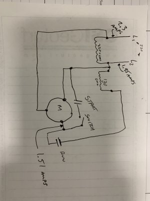
I am still studying it. From the wiring diagram lifted from Practical Machinist, it shows a star-connected primary, and a delta connected secondary where each phase is put through a series capacitor (W). That circuit is the welder, and I am not sure of the value of the capacitors on the way to the rectifier. This is a three-phase welder before messing with it to introduce capacitors into the primary. Also shown is the connections to convert to the Haas-Kamp method.

In normal 3-phase, the phases are 120° apart. The Haas-Kamp connection uses two windings on a single phase core, one connected "backwards", to deliver two phases 180° apart. Then, in the style of motor-starting capacitors, a third phase is contrived by using a 90° phase shift from capacitors, except they have to run the full AC current all the time, not just when starting. The vector diagram shows the phase relationships.

It would appear that the sequence is 0°, 90°, 180°, --repeat. It would be a "sort of" three phase, I think, and I hope I do not understand it wrong.
It can deliver energy, and I suppose adding a couple of capacitors, and re-working some primary connections is a fast, and relatively low cost dodge to make a 3-phase welder accept a single phase input.

I can believe that if I was trying it, the switch-on moment would involve a hard swallow, eyes shut, face tucked onto shoulder, arm at full extent to the ON switch, left hand fingers firmly crossed, and silent invocations to Jesus, Mary, Allah, Thor, Buddah and Zeus and any others to please make it go well!

Wiring Diagram_5902.jpg - - Haas-Kemp Conversion.png
 
Last edited:
I can believe that if I was trying it, the switch-on moment would involve a hard swallow, eyes shut, face tucked onto shoulder, arm at full extent to the ON switch, left hand fingers firmly crossed, and silent invocations to Jesus, Mary, Allah, Thor, Buddah and Zeus and any others to please make it go well!
I like this part of your reply! That is how I felt the first time I tried turning on my rotary.:eek:
 
Time to revive and finish this thread. I poked around online more and found another schematic. I built something similar to it, and sure enough a 3 phase motor started right up. At first I thought I had essentially built a static converter, but after measurements, found that I had about 240v line to line on all three wires and amp draw on all three. I think with some more careful balancing I could get the amp draw more symmetrical. I wish I had a four channel oscilloscope to see the phases, but I don’t. I did only run a motor for a couple minutes and unloaded, so I don’t know how the performance would be long term. Here is the pic I found online describing the technology, my schematic, and the transformer I used.
 

Attachments

  • 77896FC4-8E42-4D66-9AAA-8A91CA947C5E.jpeg
    77896FC4-8E42-4D66-9AAA-8A91CA947C5E.jpeg
    2.3 MB · Views: 15
  • E8AE44CD-8A28-45DE-B6D3-31B2C4B579E5.jpeg
    E8AE44CD-8A28-45DE-B6D3-31B2C4B579E5.jpeg
    2.8 MB · Views: 16
  • 3C882F11-B0D4-406A-98CA-F9E547956A2A.jpeg
    3C882F11-B0D4-406A-98CA-F9E547956A2A.jpeg
    845.3 KB · Views: 16
In normal 3-phase, the phases are 120° apart. The Haas-Kamp connection uses two windings on a single phase core, one connected "backwards", to deliver two phases 180° apart. Then, in the style of motor-starting capacitors, a third phase is contrived by using a 90° phase shift from capacitors, except they have to run the full AC current all the time, not just when starting. The vector diagram shows the phase relationships.

It would appear that the sequence is 0°, 90°, 180°, --repeat. It would be a "sort of" three phase, I think, and I hope I do not understand it wrong.
It can deliver energy, and I suppose adding a couple of capacitors, and re-working some primary connections is a fast, and relatively low cost dodge to make a 3-phase welder accept a single phase input.
Took me a while to figure this one out myself. The trick is that the neutral "floats", which is why referencing neutral (or ground) doesn't work in converted 3 phase. If A and B are your utility legs, and C is 90 degrees out of phase with A and B, you can still have an equalateral triangle A-B-C. If you used that to drive a Y connected motor you'd find the center point wasn't at the same voltage as the utility ground/neutral. That Y center would be at the center of your A-B-C triangle, and A, B, C are 120 degrees out of phase from that point.

We get too accustom to thinking of "ground" as absolute. I learned in an RF lab to not make that assumption. A good example is two ground rods should be at zero potential relative to each other, right? What if a tree somewhere between them gets struck by lightening? Still took me a while to figure out the three phase angles.
 
Last edited:
Time to revive and finish this thread. I poked around online more and found another schematic. I built something similar to it, and sure enough a 3 phase motor started right up. At first I thought I had essentially built a static converter, but after measurements, found that I had about 240v line to line on all three wires and amp draw on all three. I think with some more careful balancing I could get the amp draw more symmetrical. I wish I had a four channel oscilloscope to see the phases, but I don’t. I did only run a motor for a couple minutes and unloaded, so I don’t know how the performance would be long term. Here is the pic I found online describing the technology, my schematic, and the transformer I used.
Even without an oscilloscope, I think it is possible to figure out phase lags using voltmeter relative to a temporary artificial measurement "ground" made from three equal value resistors with a common middle connected to real earth. Choose values which will not get smoking hot! It is just a measurement. 1mA or or so is enough. This in addition to measuring floating voltages phase to phase. It does involve then drawing phase diagrams triangles to discover the phase angle lags.

The same 3-resistor trick can let you use a 2-Channel oscilloscope. Make any one phase the "reference", and then check the second and third phases relative to it. This is what my mind is telling me. Properly, I should be trying it out before I write such stuff, but I don't have one of those around. It is what I fully expect to happen if I were to try it. :)
 
Back
Top