Anybody ever do Compound indexing for an oddball division with an indexer?

xalky

Registered
Registered
Joined
Jun 17, 2012
Messages
2,220
I have to make a 113 tooth change gear for one of my lathes. 113 teeth is not divisible by anything which means I have to use compound indexing. I looked it up in the machinery's handbook on the tables but I can't make any sense of it. I will have to make some other oddball sizes in the future and would like to figure out how to do this with indexing plates. Maybe I should give up on that idea and just use " degrees, minutes and seconds" method instead, which seems a lot easier for me to figure out. Any pros want to enlighten me?

Marcel
 
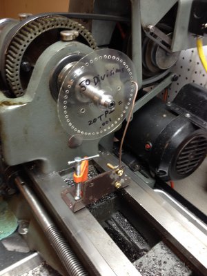
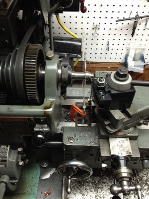
Harold Hall's "Dividing" book is a wealth of information, and I'm still trying to wrap my mind around a lot of it. But (and I'm not sure this helps, but...), this is how I divided by 50 without dividing equipment for the dial I made for my boring head:
13802423784_1b1fa7184a_o.jpg 13802512404_e3be1346c3_k.jpg

I used the DRO on my mill and a plastic CD topper on a simple arbor. Mr. Hall also shows in the book how to get coordinates via CAD or a spreadsheet, but you'd probably want a smaller drill and a larger disk to work from. I will say that it did work well for my intended purpose. I have no idea if it helps, but I'm throwin' it out there in case it does.

-Ryan

13802423784_1b1fa7184a_o.jpg 13802512404_e3be1346c3_k.jpg
 
I have to make a 113 tooth change gear for one of my lathes. 113 teeth is not divisible by anything which means I have to use compound indexing. I looked it up in the machinery's handbook on the tables but I can't make any sense of it. I will have to make some other oddball sizes in the future and would like to figure out how to do this with indexing plates. Maybe I should give up on that idea and just use " degrees, minutes and seconds" method instead, which seems a lot easier for me to figure out. Any pros want to enlighten me?

Marcel

I've used " degrees, minutes and seconds" method quit a bit and it works well, easy to get mixed up though, I use an excel spreadsheet to generate each position, it's slow and tedious but it will get you where you need to go.

Edit: here's an example of what I mean.
Edit: I just noticed I didn't word it the right way in my original post I use 100th's, my rotary table reads to 10th's and I guess the 100th's.
 

Attachments

  • HK500 31T Gear.xls
    7.5 KB · Views: 17
Last edited:
Thanks for all the answers guys. I didn't even think about printing out a division wheel. When I initially posted this question, my thoughts were to use the indexing plates that came with my rotary table, of which I have several, but it seems that I would end up with the last tooth being off by a very little, but it seemed very complicated to me.:nuts:

I use this printable "wheel divider": http://www.cgtk.co.uk/metalwork/divider

Just enter 113 elements and print it out, glue it to something and attach to your spindle or ??? Modify the print size to make it fit your diameter.
I like this solution the best, a simple solution for a simple mind, like me.:))

Can you not use a set up for 226 divisions and skip every other hole?
I don't see how that would make it easier....why not just use the 113 holes and be done with it? I guess the math might be a little easier, but with the printable wheel, who cares.:))

This was gonna be an exercise with my divider plates, but quite frankly, I'd rather do it the easiest way possible. To that end, I already have a 113 tooth gear that I can use to index off of for this particular gear, but I also want to do a few others. There's a 127 tooth gear that I want to make and also a 71 tooth gear that I don't have patterns to work off of.

The gears are metric 1.5 module with a 20 degree pressure angle. I just ordered the cutter set. This will be my first gear hobbing experience, this should be interesting. Figuring out the Blank size OD is not a big deal using the formulas in the Machinerys Handbook.

Thanks again guys.

Marcel
 
I don't have a video camera to show how it's done so I'll try to explain compound indexing as best I can remember.

If your dividing head is 40 to 1, for 113 divisions you would need a index plate with 47 and 49 holes.
You need to turn the handle 3 26/47 minus 18/49 turns,
So you would set the sector arms for 26 holes, turn the crank 3 turns plus 26 holes on the 47 hole circle and drop the pin to lock it there.
Then you need to turn the whole index plate and crank handle assembly the opposite direction 18 holes on the 49 hole circle. On my Brown and Sharpe universal head there is a locking pin on the back side of the index plate that allows you do this. Other brands may vary.
Lock the spindle take your cuts.
Repeat 112 times.

I hate doing compound indexing so I have set of the high number index plates that have the prime numbers from 51 to 149 so I can just move the crank 40 holes for something like cutting a 127 tooth gear.

I would suggest that you make a index plate with 71, 113 and 127 holes.
 
Ok, now I get it........screw that! That's way too much like work.

When I was looking it up on the chart I saw the 3 26/47-18/49 , it just wouldn't compute. That's a very difficult way to get to the next spot. Way more than what I want to have to think about.

Your explanation was perfect BTW.
 
After reading through this thread, I understand why CNC was invented. This makes my head hurt.:phew:
 
Back
Top