-
Welcome back Guest! Did you know you can mentor other members here at H-M? If not, please check out our Relaunch of Hobby Machinist Mentoring Program!
You are using an out of date browser. It may not display this or other websites correctly.
You should upgrade or use an alternative browser.
You should upgrade or use an alternative browser.
Another Tool & Cutter Grinder
- Thread starter Mark_f
- Start date
I got the rest of the parts for my column assembly and did some work on it today.
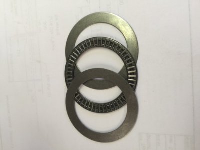 This is a 2" ID bearing assembly from McMaster Carr. It will reside on the column base to make it "float"
  when I turn it.
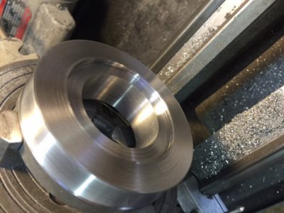 I machined a pocket in the column base so that the bearing sits .002" proud leaving the column "float" when unlocked. The lock will clamp the base tight to keep it in position.
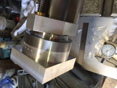
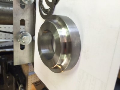 This is the finished column base. It is made from a piece of 12L14 steel , 4" in diameter and 1" thick. It is a snug sliding fit on the 2" column and held securely with a 1/4-20 set screw.
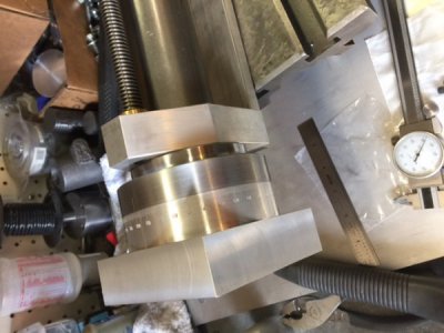 This is the column base assembled.
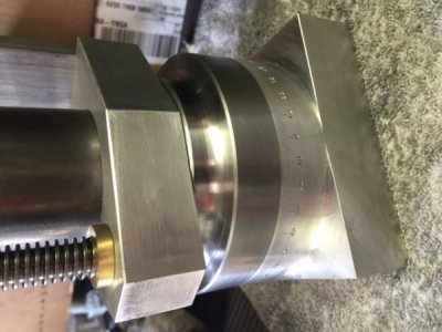
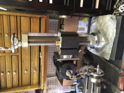 I assembled the grinding head to the column. It works perfectly. The elevation screw turns smooth and easy. The head moves up and down smoothly. Paying close attention to tolerances has paid off here. The complete assembly turns effortlessly on the bearing. I cannot detect any back lash at all.
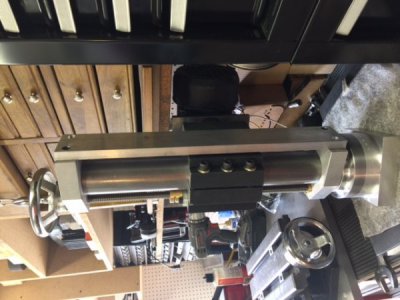 In this view , you can see the support bar I added. This bar was not really needed but it does add a lot of stability and it looks good. It will get the black wrinkle finish.
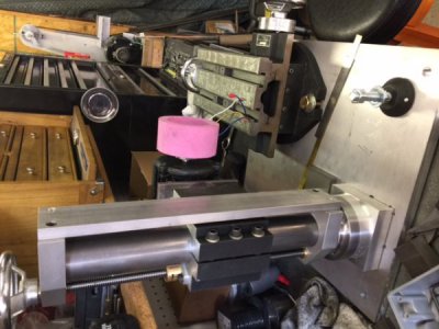 The next important thing is to determine the best position for the column in relation to the table. In this photo , the column is turned to the position for grinding flutes (if using a cup wheel ). A flat grinding wheel will require the column to be rotated 90 degrees from this position. The table has to be able to get close to the wheel in either position. While it will work in a stationary position, I will be making the column able to move forward and backward in a 4 inch travel range. This will give the grinder a lot more versatility which will be a big help grinding specialty cutters like mill cutters.
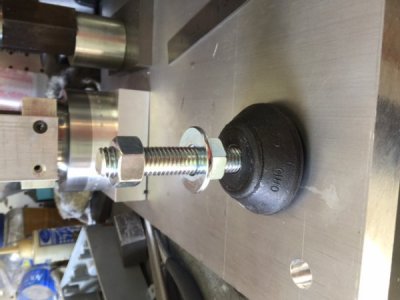 This is one of the anti-vibration leveling feet acquired from McMaster Carr. they are 2 3/16" in diameter with a 1/2-13 stud.
I have discovered that I cannot lift the grinder when all parts are assembled. This probably means I will have to assemble it on the bench where it will reside.
 This is a 2" ID bearing assembly from McMaster Carr. It will reside on the column base to make it "float"
  when I turn it.
 I machined a pocket in the column base so that the bearing sits .002" proud leaving the column "float" when unlocked. The lock will clamp the base tight to keep it in position.
 This is the finished column base. It is made from a piece of 12L14 steel , 4" in diameter and 1" thick. It is a snug sliding fit on the 2" column and held securely with a 1/4-20 set screw.
 This is the column base assembled.
 I assembled the grinding head to the column. It works perfectly. The elevation screw turns smooth and easy. The head moves up and down smoothly. Paying close attention to tolerances has paid off here. The complete assembly turns effortlessly on the bearing. I cannot detect any back lash at all.
 In this view , you can see the support bar I added. This bar was not really needed but it does add a lot of stability and it looks good. It will get the black wrinkle finish.
 The next important thing is to determine the best position for the column in relation to the table. In this photo , the column is turned to the position for grinding flutes (if using a cup wheel ). A flat grinding wheel will require the column to be rotated 90 degrees from this position. The table has to be able to get close to the wheel in either position. While it will work in a stationary position, I will be making the column able to move forward and backward in a 4 inch travel range. This will give the grinder a lot more versatility which will be a big help grinding specialty cutters like mill cutters.
 This is one of the anti-vibration leveling feet acquired from McMaster Carr. they are 2 3/16" in diameter with a 1/2-13 stud.
I have discovered that I cannot lift the grinder when all parts are assembled.


- Joined
- Mar 3, 2014
- Messages
- 634
Such well planned and beautiful work.
Your post will be a excellent reference for us all.
I think the pictures load with a long edge at the bottom and top. How you crop could be the cause of rotation.
Your post will be a excellent reference for us all.
I think the pictures load with a long edge at the bottom and top. How you crop could be the cause of rotation.
As I was mocking up the assembly for the grinder to locate the best position for the column to be in the correct position with the spindle in a normal mode and inverted mode, I noticed while it can be done, the machine would be much more versatile if the column could be moved over a range of positions. This would make it easier to setup for special cutters such as milling cutters. with this in mind, I designed a set of guide rails that locate the column, let it move back about 1 inch or forward about 3 inches. the guide rails will also clamp the column in position. This requires more work and some precise milling, but will be worth the effort.
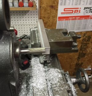 The guide rails are milled from 1" square aluminum bars 8" long. The get a .495" step , .260" deep. Then a other step for clearance milled in the top. There will be a slot in each side of the column base to accept the rails.
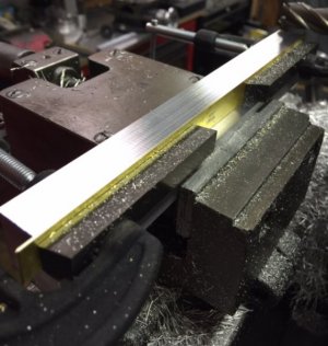 There will be a brass gib on each rail where it contacts the column base. To get these to fit exactly, I clamped the brass gib in the rail and finish milled the bottom with the gib in place. this made everything match and assured the rail was parallel because all the milling was done without removing the rail.
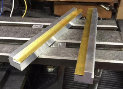 These are the finished guide rails and gibs.
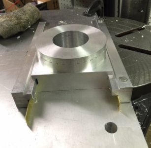 The first guide is installed in place. There are two .375" dowel pins, one in each end. You can see in the photo, there is a small gap at the bottom of the rail. this is so the three SHCS ( they are not drilled and tapped yet) can clamp the guide down and lock the column. The dowel pins let the rail move up and down slightly while keeping it accurately located. The dowel pin holes are reamed to "on size" and are a good fit.
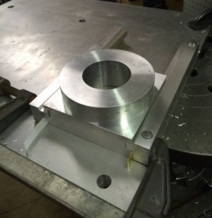 As I get ready to drill the dowel pin holes for the other guide rail, You can see a strip of paper in between the gib and the column base. This is to provide .002" clearance on the gibs so the column can slide when the rails are loosened. ( the paper will be removed
  ) There will be three 1/4-20 SHCS on each rail to lock it down and clamp the column. You can also see in this photo the clamp holding the assembly tight together while drilling. Tomorrow, I will drill the bolt holes and finish this step. Oh..... and the brass gibs will be trimmed to length.
 The guide rails are milled from 1" square aluminum bars 8" long. The get a .495" step , .260" deep. Then a other step for clearance milled in the top. There will be a slot in each side of the column base to accept the rails.
 There will be a brass gib on each rail where it contacts the column base. To get these to fit exactly, I clamped the brass gib in the rail and finish milled the bottom with the gib in place. this made everything match and assured the rail was parallel because all the milling was done without removing the rail.
 These are the finished guide rails and gibs.
 The first guide is installed in place. There are two .375" dowel pins, one in each end. You can see in the photo, there is a small gap at the bottom of the rail. this is so the three SHCS ( they are not drilled and tapped yet) can clamp the guide down and lock the column. The dowel pins let the rail move up and down slightly while keeping it accurately located. The dowel pin holes are reamed to "on size" and are a good fit.
 As I get ready to drill the dowel pin holes for the other guide rail, You can see a strip of paper in between the gib and the column base. This is to provide .002" clearance on the gibs so the column can slide when the rails are loosened. ( the paper will be removed
  ) There will be three 1/4-20 SHCS on each rail to lock it down and clamp the column. You can also see in this photo the clamp holding the assembly tight together while drilling. Tomorrow, I will drill the bolt holes and finish this step. Oh..... and the brass gibs will be trimmed to length.
I GOT THE PHOTOS TO LOAD RIGHT!!!!!!! FINALLY. I take the photos with my iphone and it makes photos called "full rendering", whatever that means. I have to edit each photo and crop it slightly or not at all, but must go through the crop process and save the photo. Then it will load correctly. Thank you tertiaryjim for the idea.
Thank you. Yes, I have a basic design for most of my projects but as I get building, I discover or think of new features I want and have to kind of design on the fly and build by seat of my pants, so to speak. But I have to figure the best way to achieve that goal. When looking at a finished project, for me, it has to look professional and have obvious quality.Pretty inspiring watching you engineer this on the fly. Really nice work. Mike
Today I finished the sliding column base.
e.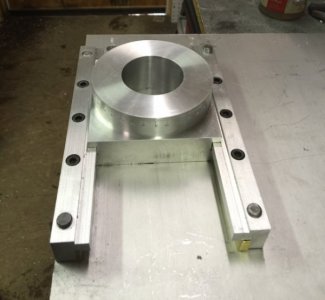 There are three lock screws on each side. the 3/8" dowel pins work great as a guide for the rails to float up and down to lock and unlock without moving or losing position. the brass gibs worked great also. when unlocked the column base slides stiff because of the extremely close fit but smoothly. I couldn't ask for better results. It was a lot of work to make this, but well worth it. The column can be moved back 1" or forward up to 3".
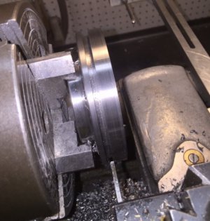 Next on the agenda was to make a way to lock the column rotation in position. The column needs to free to rotate 360 degrees and able to lock in any position securely. I mounted the column base ring in the lathe and cut a slot all the way around .200" wide and .170" deep. This is where the locks will clamp down.
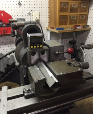 The locks are machined from 1" square steel bar. I needed a way to mill of at a 45 degree angle, so this is what I came up with. I put the square bar in my mill vise clamping on two corners. I set a V block on the bar with my angle Gage and set to read zero degrees. this set the bar at a perfect 45 degrees for milling. After milling , I sawed the piece off and set up again to make the second one. The next photo is the finished lock.
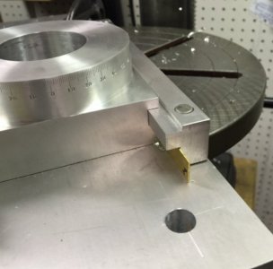
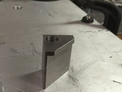 I milled this lock from 1" square CRS, drilled and counter bored for a 1/4_20 SHCS.
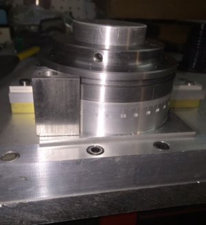 The lock fits on the corner of the column base and engages the groove cut in the column ring. Tightening the bolt clamps down the column.
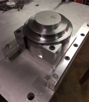 While one clamp is sufficient to do the job, I made two and put one on each rear corner. they are easily accessible and out of the way. They work excellent. This is a simple but effective locking system, easy to make and looks nice too. When unlocked the column floats on the needle bearing and turns very easy. This whole system is very close tolerance and works smoothly with no detectable play or excess movement and locks in position securely. I am very pleased with it. You can see in the above photo, I bent the ends of the brass gibs around the rail ends. this keeps them from moving when sliding the column forward or back. Now i can remove the temporary plug and put the column with the grinding head back on.
e.
 There are three lock screws on each side. the 3/8" dowel pins work great as a guide for the rails to float up and down to lock and unlock without moving or losing position. the brass gibs worked great also. when unlocked the column base slides stiff because of the extremely close fit but smoothly. I couldn't ask for better results. It was a lot of work to make this, but well worth it. The column can be moved back 1" or forward up to 3".
 Next on the agenda was to make a way to lock the column rotation in position. The column needs to free to rotate 360 degrees and able to lock in any position securely. I mounted the column base ring in the lathe and cut a slot all the way around .200" wide and .170" deep. This is where the locks will clamp down.
 The locks are machined from 1" square steel bar. I needed a way to mill of at a 45 degree angle, so this is what I came up with. I put the square bar in my mill vise clamping on two corners. I set a V block on the bar with my angle Gage and set to read zero degrees. this set the bar at a perfect 45 degrees for milling. After milling , I sawed the piece off and set up again to make the second one. The next photo is the finished lock.
 I milled this lock from 1" square CRS, drilled and counter bored for a 1/4_20 SHCS.
 The lock fits on the corner of the column base and engages the groove cut in the column ring. Tightening the bolt clamps down the column.
 While one clamp is sufficient to do the job, I made two and put one on each rear corner. they are easily accessible and out of the way. They work excellent. This is a simple but effective locking system, easy to make and looks nice too. When unlocked the column floats on the needle bearing and turns very easy. This whole system is very close tolerance and works smoothly with no detectable play or excess movement and locks in position securely. I am very pleased with it. You can see in the above photo, I bent the ends of the brass gibs around the rail ends. this keeps them from moving when sliding the column forward or back. Now i can remove the temporary plug and put the column with the grinding head back on.
I have a new delima...delema.....oh crap...problem (can't spell it). I posted this question in the questions and answers forum.:
I need some opinions here. I am interested in using ER 40 collets on my south bend 9" lathe. I can make a holder that screws on the spindle and would have the 3/4" through hole capacity, BUT, I can buy a 3 MT ER 40 chuck that will fit into the 3 MT spindle taper for $50. The only drawback is , it only has a 1/2" through hole capacity. I am trying to figure which is the better option. I don't know what to do. Any opinions here?
Also.....I'm not sure but with the MT adapter...some use a draw bar. That would kill the through hole.
NOW! I am going to expand my question here. The collets would be nice on my lathe, BUT, the air bearing on this tool grinder uses 5C collets. I have a small set to 1" by 1/8" steps. I will need a bigger set for this grinder which is costly and they are really only good on this grinder as they won't fit my lathe. There is a 5C to ER 40 chuck available that would convert my air bearing to ER 40 collets for about $50. Then I could use the ER collets on both machines saving money by only buying one set of collets. HOWEVER, I am concerned about the added length using the adapter ( which I don't believe would be a problem) and losing accuracy. The only other solution is spend a butt load of money I don't have for two different collet sets. I AM SO CONFUSED I don't know what to do. ( or am I overthinking this )
I need some opinions here. I am interested in using ER 40 collets on my south bend 9" lathe. I can make a holder that screws on the spindle and would have the 3/4" through hole capacity, BUT, I can buy a 3 MT ER 40 chuck that will fit into the 3 MT spindle taper for $50. The only drawback is , it only has a 1/2" through hole capacity. I am trying to figure which is the better option.
 I don't know what to do. Any opinions here?
Also.....I'm not sure but with the MT adapter...some use a draw bar. That would kill the through hole.
NOW! I am going to expand my question here. The collets would be nice on my lathe, BUT, the air bearing on this tool grinder uses 5C collets. I have a small set to 1" by 1/8" steps. I will need a bigger set for this grinder which is costly and they are really only good on this grinder as they won't fit my lathe. There is a 5C to ER 40 chuck available that would convert my air bearing to ER 40 collets for about $50. Then I could use the ER collets on both machines saving money by only buying one set of collets. HOWEVER, I am concerned about the added length using the adapter ( which I don't believe would be a problem) and losing accuracy. The only other solution is spend a butt load of money I don't have for two different collet sets. I AM SO CONFUSED
 I don't know what to do. ( or am I overthinking this )
Last edited by a moderator:

