Another electromagnetic chuck question.

Tim9

H-M Supporter - Sustaining Member
H-M Platinum Supporter
Joined
Oct 11, 2015
Messages
1,197
So, I bought an old Parker Majestic 618 Surface Grinder. From the serial number I’m thinking it’s about 1948 Vintage.
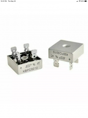
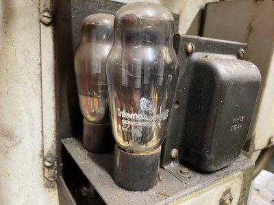
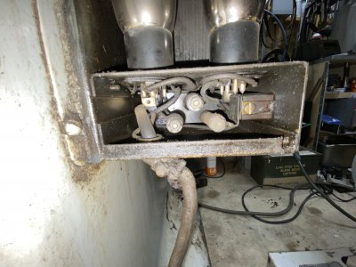
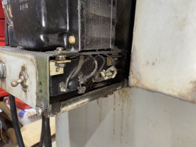
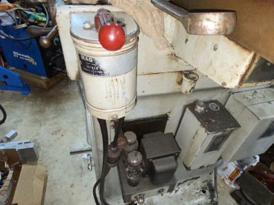
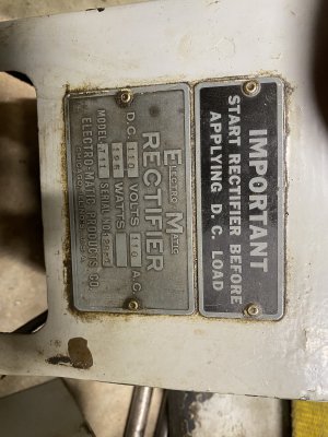
It came with a disconnected ( cut wires ) Taft Peirce 12” chuck and and all of the original electrical boxes and relays for the magnetic chuck. And, the DC Rectifier is driven by a transformer and two vacuum tubes.
Since the Electromagnetic control switch appears intact, I’d like to keep this as simple as possible. The chuck is rated at 110 volts and 125 watts. Basically 1 amp DC at @ 100 to 110 volts
 

Attachments

  • 3D831B70-964D-4920-AB26-6ED113073C90.jpeg
    3D831B70-964D-4920-AB26-6ED113073C90.jpeg
    3.1 MB · Views: 11
  • F9645FCC-40E0-4AFC-8729-9917F76CC5EF.jpeg
    F9645FCC-40E0-4AFC-8729-9917F76CC5EF.jpeg
    2.9 MB · Views: 11
  • 91E00433-FB83-45DD-8334-E836493D12ED.jpeg
    91E00433-FB83-45DD-8334-E836493D12ED.jpeg
    3.3 MB · Views: 10
  • B0F10913-ACC7-4FC2-9228-8F6EB2703B69.jpeg
    B0F10913-ACC7-4FC2-9228-8F6EB2703B69.jpeg
    2.8 MB · Views: 10
  • F7495ABD-2E1C-437B-8188-EB1626B96321.jpeg
    F7495ABD-2E1C-437B-8188-EB1626B96321.jpeg
    2.1 MB · Views: 9
Last edited:
So, my question is this. Can I just remove the two tubes and replace them with a Full Wave Bridge Rectifier. I haven’t even checked the transformer but visually it looks okay. If I were to power up the transformer side with 110v ac , I am guessing that I’d have ac voltage going into one of tube terminals. And I’d hook that into the wavy sides of the bridge rectifier. From what I’ve found online, the way this DC rectifier worked was each tube provided half of the output to the chuck. Something around 45 watts each tube.
Does any of the above make sense. Or am I totally off base here.
 
By the way. The tube has four terminals so I’m guessing two of them are 110v ac in and the other two are dc+ and dc-
Im guessing that’s it. So depending on the output of the transformer, I’ll either put one bridge rectifier in it or use two of them coming right from the 4 tube terminals.
 
The simple answer is you will be doing something like that.

Your prudent measure is to trace the entire circuit so you don't end up with any nasty surprises. Some older units only did half-wave rectification, and you should stick to what they did, unless you change out the entire control unit.
 
Dabbler….thanks for the reply. That’s kind of where my head was at but I just wanted to run it by this forum before I go that route. I plan on getting out my Volt Ohm meter and checking everything first. But I just wanted to make sure if it all checked out okay….then a bridge rectifier could replace the tubes.
 
This is most likely what you have, basic full wave rectifier with vacuum tubes

View attachment 366638

The modern equivalent with diodes

View attachment 366639
Jim….that top diagram is basically showing just one vacuum tube ?

fwiw… I already have a box of 50 amp rectifier bridges in the metal casing. Probably 600 volt.

look like these.

but if I need half wave reduction I’ll get a couple of those. I think I’m on the right track. I’ll post more tomorrow if I get stumbled. Thanks again guys.
 

Attachments

  • B4B86604-5878-4B2B-B00D-3D78ED41C7F7.png
    B4B86604-5878-4B2B-B00D-3D78ED41C7F7.png
    767 KB · Views: 10
Last edited:
I think the upper tube drawing is shown as a positive ground connection, whereas the lower diagram shows negative ground. But it's the same basic circuit regardless.
-Mark
 
Jim….that top diagram is basically showing just one vacuum tube ?

fwiw… I already have a box of 50 amp rectifier bridges in the metal casing. Probably 600 volt.

look like these.

but if I need half wave reduction I’ll get a couple of those. I think I’m on the right track. I’ll post more tomorrow if I get stumbled. Thanks again guys.

Those will work fine, but you need to confirm the center tapped transformer and connect like below.

1621571743049.png
 
Back
Top