

Sigh, I hate to add another drum switch post to the clutter, but I've been staring at wire diagrams for a couple hours now and can't work out what needs to be done.
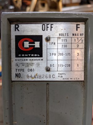
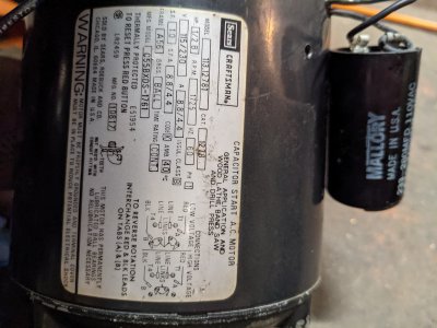
My clausing lathe is currently running nicely on a craftsman motor and cutler hammer drum switch at 110v. I've just finished adding some additional 220v drops to my garage and am attempting to change over the dual voltage, thermally protected, capacitor start motor from 110v to 220v. Looking at the motor wiring diagram it was simple enough to change the windings over from parallel to series, but the drum switch wiring has me stumped. I can't figure out how to wire it such that both hot wires are shut off when the switch is off.
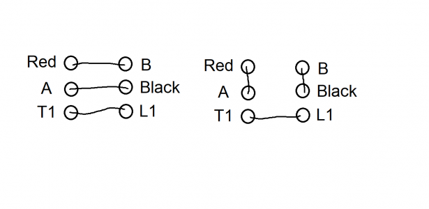
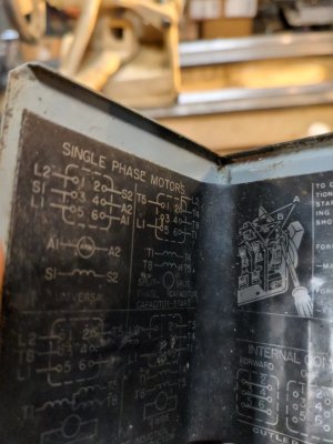
The motor plate sways to swap red and black wires on spade connectors "A" and "B" to reverse direction. Intuitively the drum switch is currently wired with Red, Black, A, and B in the top 4 positions (diagram attached) with the hot wire from my plug occupying the bottom position to switch power to T1 on the motor. The neutral from my plug currently goes directly to T4 on the motor.
I imagine this setup would still work just fine if I replaced the neutral wire at T4 with the second hot wire from my new 220v source, but I would then still have one 110v leg connected in the off position which doesn't sit right with me. I could add a secondary disconnect but thats much less clean.
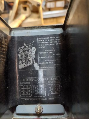
I believe there should be a way to do this with just a drum switch but can figure it out. I suspect that it may require digging deeper into the motor itself to suss out some additional leads that are on the underside of the board or replacing the switch with a different type.
Some guidance here would be much appreciated.
My clausing lathe is currently running nicely on a craftsman motor and cutler hammer drum switch at 110v. I've just finished adding some additional 220v drops to my garage and am attempting to change over the dual voltage, thermally protected, capacitor start motor from 110v to 220v. Looking at the motor wiring diagram it was simple enough to change the windings over from parallel to series, but the drum switch wiring has me stumped. I can't figure out how to wire it such that both hot wires are shut off when the switch is off.
The motor plate sways to swap red and black wires on spade connectors "A" and "B" to reverse direction. Intuitively the drum switch is currently wired with Red, Black, A, and B in the top 4 positions (diagram attached) with the hot wire from my plug occupying the bottom position to switch power to T1 on the motor. The neutral from my plug currently goes directly to T4 on the motor.
I imagine this setup would still work just fine if I replaced the neutral wire at T4 with the second hot wire from my new 220v source, but I would then still have one 110v leg connected in the off position which doesn't sit right with me. I could add a secondary disconnect but thats much less clean.
I believe there should be a way to do this with just a drum switch but can figure it out. I suspect that it may require digging deeper into the motor itself to suss out some additional leads that are on the underside of the board or replacing the switch with a different type.
Some guidance here would be much appreciated.
Attachments
-
 drum switch wiring.png17.2 KB · Views: 10
 -
 PXL_20210114_010833694.MP.jpg6.8 MB · Views: 14
 -
 PXL_20210114_010919215._exported_827_1610589821286.jpg3 MB · Views: 9
 -
 PXL_20210114_010842395._exported_1598_1610589854036.jpg424 KB · Views: 11
 -
 PXL_20210114_010850819._exported_1633_1610589842167.jpg401.8 KB · Views: 10