- Joined
- Nov 17, 2017
- Messages
- 1,525
This post is a question about how to achieve repeatability--making several parts fit the same blueprint.
But first some background::
I am building several telescopes from 13" to 20" to 30" diameter apertures. I bought my milling machine and lathe in order to be able to hit better accuracies, I also bought some dial indicators, calipers, a set of micrometers, and a few other things of metrology. In many respects, I am doing "all right" and in a few I keep running into the "how did that happen" category. All of the machined material in this post is 6061T6 of extruded bar stock.
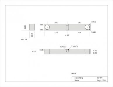
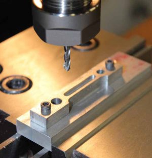
The 13" mirror cell has 6-points that through the back side of the mirror. These 6 points are on 3 balance beams. In rough numbers the beams are 4.2" long, 0.600" wide, and 0.500" tall. I can routinely rough 3/4*3/4 stock into the required dimensions within 0.0015" measured at 9 places around the parts and have 3 parts that are all within 0.0005 to 0.0015 of each other. All well and good.
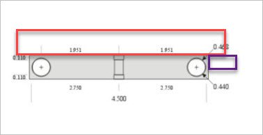
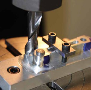
At both ends of the beam I drill (0.4375) trying to get both holes exactly 3.902" apart (or as close as I can make them). After drilling and without moving the part, I switch from drilling to the boring head and bore the hole to 0.468 which is a "bearing fit" to the 12mm ball transfers that touch the back side of the mirror at very low friction levels. I start with beams that are long enough that the accuracy of the holes on (say) the left end of the beam are not critical as long as these holes are the same away from that end of the beam. When the part goes into the vise, it is supported on parallels and another parallel is clamped to the vise so that the left edge of the part can be positioned easily. The bored holes have been measured with a snap gauge and the micrometers and I am seeing a similar 0.0015"-0.002" variation in the bearing fits of these holes.
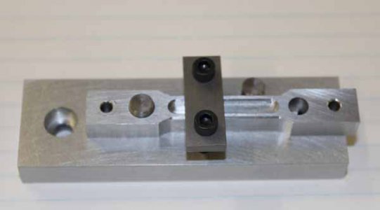
After drilling and boring all three beams, I position the table so that it has moved 3.902". I confirm this by making the first hole in a sacrificial material and measure the near sides and far sides of said hole, the average of which is the center to center distances. These are all measured with a dial caliper. I then clamp down the table, insert each part, drill and bore each part. After wards, I measure the overhang off the ends of the part and edge mill the beams to final length centered around the bored holes.
At this point I have 3 parts: one with 3.9025" hole spacing, one with 3.9015" hole spacing, and one with 3.899" hole spacing. While this is better than is probably needed for the project at hand, If anyone can help me locate the point at which I lead error creep into the machine process I would be appreciative.
After milling the beams to length such that the material from the far end of the hole to the edge of the beam is "the same" (about 0.016" as accurately as I can measure it), I use the beam length to find the center of the beam and drill an axial hole perpendicularly through the beam. I proceed to drill a hole using a C drill (0.242") backed up with a D drill to 0.110 depth. This D drill is a nice thumb bearing fit to the miniature ball bearings (1/4×1/8×7/64) that are needed on this balance beam. The problem, here, is that the drilled hole walks about 0.002" while passing through the beam. This puts the axis off center of the beam, and makes balancing the beam in 2 dimensions extraordinarily hard. Here the question is how does one get holes on one side of a part to match up to a hole on the other side of the part to (say) 1/2 a thou? at these tiny dimensions? how does one bore a bearing fit at this kind of dimension (I don't know where to get the tooling to do bores at this size)?
The numbers above are after making this set of beams 3 times and learning the more obvious mistakes of part positioning and tolerance stackups. As I said, the current parts are usable, but future machine parts will not be so tolerant of litter errors of part position prior to machining.
Thanks in advance.


