A crazy thought and potential project.

That sounds very high for precision tapered rollers (unless you are specifying a huge spindle bore). For something around 12" swing size, and a 3/4 hole through spindle, I would expect closer to $150 per bearing. You should be able to get a matched set of ABEC-7 angular contact bearings for under $300 (name brand).

Keep in mind total cost, if you go with bronze bushings, you are going to want to harden the shaft, which means grinding afterwards. Unless you have the facilities to do this yourself, that is going to add to the total cost of the spindle assembly, and likely put you back to where you would be with AC or tapered rollers.
 
I was looking around for machines and looking at a couple of resources for said companies of the machines, I want to try something probably incredibly costly and time consuming but I am a person that likes to tinker. I am also someone that likes big and involved projects. The idea I had was to try to make at least a bench lathe from scratch. From cast parts to machining most of the components that I can. Granted this will cost more than purchasing one from the cheap asian imports but with a better chance of higher quality. Maybe if everything goes well, I might look into making full size machines to say "yes I built my own machines to work on". I want to look at what I would need, NOT how impossible it would be. I understand this is a HUGE project to do but I would like to see the results of it.

There is a site on Yahoo groups that will give you a ton of help doing exactly what you are looking to do. I say go for it and learn all you can and have a great time doing it. It is possible and fairly easy to build a lathe and milling machine. The site is : https://groups.yahoo.com/neo/groups/Multimachine-Concrete-Machine-Tools/info. They have been developing many ways to skin that cat and can help you out if you need it.

Bob
 
That sounds very high for precision tapered rollers (unless you are specifying a huge spindle bore). For something around 12" swing size, and a 3/4 hole through spindle, I would expect closer to $150 per bearing. You should be able to get a matched set of ABEC-7 angular contact bearings for under $300 (name brand).

Keep in mind total cost, if you go with bronze bushings, you are going to want to harden the shaft, which means grinding afterwards. Unless you have the facilities to do this yourself, that is going to add to the total cost of the spindle assembly, and likely put you back to where you would be with AC or tapered rollers.

I'm trying to do it with some relative cost to what an original would go for. I want something 1.5 to 2 inch hole through spindle, but if costs prove that too much, I would try to make it to a workable size. I'm right now at a standstill since I need room to do the necessary work. With that, I would like to find an actual film or book really detailing how one of these machines that are made from a known manufacturer, but I have no such luck with that.

Also for the bearings, since that would be a more available route to take, how would I go about to do the spindle? I had worked on South Bend H10 lathes and Kent's, and I want to know how hard would it be to machine a spindle for one of those to be able to mount multiple jaw chucks and still have a way to attach collet?

Edit: It was the high precision ball bearing assemblies.
 
Last edited:
I don't know of a book that is going to tell you that, lots of it is "trade secret" sort of stuff. If you have the most accurate, or cheapest precision spindle out there it's probably because of what you are doing, and how you are doing it; you're not gonna just give that info out to anybody ;)

One group that does give that info out is bearing manufacturers, mainly because they want to help you design things with bearings so they can sell their product. They have a vested interest in this. SKF and Nachi both have good material available online that describe bearing types, design tradeoffs, etc. I have been reading through all this stuff lately because I am working on designing a 4th axis for my mill. Overall design is the same as a lathe spindle. In general the choice of bearings goes something like this

1) Deep groove ball bearings for cheap (low load, low precission) spindles. This is what most small import machines come with. They work fine, and they are cheap and easily available. Not great at axial loading. Pre-loading is fiddly.
2) Angular contact bearings for high speed, high precision spindles. This is what lots of mid to high end machines use. Not as good at shock loads as tapered rollers, and not as stiff, but they do go zoooom.
3) Tapered roller bearings. They are better at shock loads, and are stiffer. Not as good for high speed spindles.
4) The works. Higher end spindles (especially heavy duty spindles) use multiple types. Typically this would be a combination between cyclindrical roller bearings for taking heavy radial loads, and sets of angular contact bearings for taking axial loads.
 
So I just have to use two or three type of bearings for the spindle. Now for the spindle itself, I had looked into the shape of general spindles, and I think that will be the hardest part to make for the head of the lathe. For the acne threads, I wonder if there's a length you could order or they have to be cut to what you demand?

Edit:

Ok found some on both Granger and MSC, they run about ~35 to 200 dollars for a 6 foot length. Now what diameter should I use with what thread size? Also, are there any that go longer?
 
Last edited:
Squatch,
If you are really looking to keep costs down, Surplus Center has acme rods dirt cheap. The pitch you use depends on what they are for. In general, 8 TPI is used on smaller lathe leadscrews (4 on larger lathes), and that is what most change gear setups are arranged for. Also, it helps to have a lead that is some nice even number of divisions in thousandths when you make your handwheels. 8 TPI gives you .125 per revolution, 10 TPI gives you .100, 5 TPI gives .200. You want to avoid things like 6 TPI for a manual machine, as it gives an uneven number of divisions for the handwheel. If the machine is CNC, it doesn't matter, you just tell the computer the pitch and it accounts for that when you move the machine. For CNC the pitch is generally chosen to give a certain movement rate such as 50 inches per minute (IPM) given a set max motor RPM, which depends on your motor and driver setup. As for diameter, that depends mainly on load and how long the screw is (and what direction the load is in). The longer the screw, the larger it needs to be to prevent buckling under compression loading. You can get a good idea by looking at the leadscrew sizes on commercially built lathes. The leadscrew can be setup to work only in tension, by fixing the leadscrew to the frame and turning the leadnut on the screw, but that is a bit of work to setup, and hard to do on a manual machine.
 
Try bearingscanada.com perhaps. You may not choose to buy them there I don't know but they have pricing online.


Sent from my iPhone using Tapatalk
 
I was looking around for machines and looking at a couple of resources for said companies of the machines, I want to try something probably incredibly costly and time consuming but I am a person that likes to tinker. I am also someone that likes big and involved projects. The idea I had was to try to make at least a bench lathe from scratch. From cast parts to machining most of the components that I can. Granted this will cost more than purchasing one from the cheap asian imports but with a better chance of higher quality. Maybe if everything goes well, I might look into making full size machines to say "yes I built my own machines to work on". I want to look at what I would need, NOT how impossible it would be. I understand this is a HUGE project to do but I would like to see the results of it.


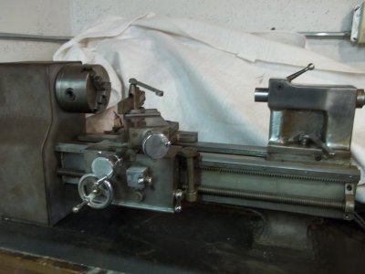
Not that huge of a project I made one from scratch with no castings when I was in my 20s here is a picture of it in its unfinished form I quit on it when I got another lathe but recently I started to finish it I have most of it painted now and I am working on the QCGB. The ways are hard chromed the carriage and tail stock have removable brass plates on them I can post some more recent photos if you would like. It has also two types of feed with a clutch. Ray

http://www.hobby-machinist.com/showthread.php?t=13850&p=108061#post108061
 
Actually I might see if I can get my school involved with this now. Figuring the most I would have to is machining the parts that I can, and probably with some of the other students in the machining class, and for the frame, have the welding class do that.

Now thinking of it, I wonder how difficult would it be to sonic weld plates together?

Also the lathe I want to do is going to be totally manual for the first one.
 
Last edited:
100_0398.JPG

It does not look like this now it has been polished and painted i just have to put mine back together I dont know enough about sonic welding this one was all old school welding and then heated annealed and straighten, I then took it over to our surface grinder and started in after that the bed and some of the other handles and knobs I made where sent to the chrome shop thats back when things where cheap. Ray

100_0398.JPG
 
Back
Top