- Joined
- Feb 1, 2015
- Messages
- 9,646
Edit: This post is edited to correct some errors, logical and otherwise. The errors arise from failing to realize when dividing a circle where the end hole doesn't coincide with the start hole, there is actually one more hole than there are divisions. Think of 12" ruler; If we wanted to divide a 12 inch line into 12 equal divisions, we would scribe a mark at each of the positions 1 -12 plus the 0 position resulting in 13 scribe marks.
The pictures were replaced with ines depcting the correct configuration
Erroneous text is colored red and lined out and replacement text is colored blue.
A discussion of how to make a divider plate for 127 equally spaced holes has come up a number of times in the recent past. The biggest roadblock is that the number of holes dictates a fairly large disk in order to locate all 127 holes on a common diameter. The workaround is drill two or three sets of holes on different diameters. A recent thread brought up a video by Tom Lipton, OxTools, where he modified a spin indexer by adding a disk at the back with the 127 holes on several diameters to accomplish the task.
What got me thinking is that a spin indexer is actually using the same principle that a vernier uses to provide nine intermediate positions in addition to the 36 hole positions on the indexer plate. That same principle can be applied to a 127 position indexer.
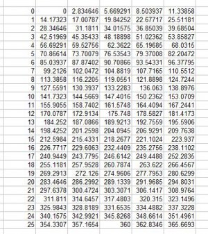
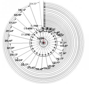
The logic goes like this. 127 holes equally spaced on a circle are 360/127 or 2.8346º apart. If we multiply that angle by 5, we get 14.1732º and if we space holes by that amount, we will end up with 25 holes plus the start hole for 26, the first at 0º and the last at 354.3307º. The end hole is8.5039º 5.6693º from completing the circle but that is of no real consequence. This makes up the main plate of the indexer. If we provide a mating plate with an index hole, we can locate every fifth position of the required 127.
Now, if we shift the indexing hole by 2.8346º, We will get the second set of25 26 positions. If we then shift the indexing hole by twice that angle from the original hole, we will get a third set of 25 26 positions. Repeating the process, we will get the fourth and fifth sets of positions, completing the 127 equally spaced positions.
Rather than offsetting the successive index holes by the 2.8346º which would mean intersecting holes, I chose to offset by 3 times that or 8.5039º. The next index hole is located at 6 times 2.8346 which is the same as 6-5 or 1 for an offset of 2.8346º. Similarly, the last two index holes are 9 x or 9-5 = 4 and 12 x or 12-2x5 =2. So although the holes will not generate positions in order, they will generate all of the 127 required positions.
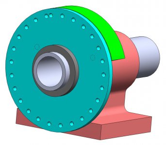
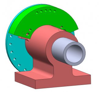
I used my Phase II spin indexer for the design. While most of the indexers should be nearly identical, it would be wise to check all dimensions prior to construction. As to actual construction, a new index plate replaces the OEM plate. In order to not destroy the original capability of the spin indexer, the new plate is larger in diameter than the original with the index holes slightly higher than the fixed boss of the indexer a second boss is located above the original, positioned using the two end index holes and 5mm dowel pins. It is held in place with two screws threaded into the spin indexer casting.
The indexer is used in the same fashion as the original version. It isn't possible to mis-locate a position but you could hit a position twice. The easiest way is to locate the first25 26 positions with the first index hole and then move to the second index hole for the second 25 26 positions and repeating for the remaining positions.
Finally, a spin indexer is not required as a starting point. The same function can be realized with two plates and an axle
disclaimer: I offer this up as a solution for someone with limited resources. I have a CNC mill with 4th axis capability and can easily recreate the function of a dividing plate. As such, this is more a thought experiment. I used my Phase II for measurements and believe that they are correct but anyone intending to make this modification should use care to ensure that their design is consistent with their spin indexer.


The pictures were replaced with ines depcting the correct configuration
Erroneous text is colored red and lined out and replacement text is colored blue.
A discussion of how to make a divider plate for 127 equally spaced holes has come up a number of times in the recent past. The biggest roadblock is that the number of holes dictates a fairly large disk in order to locate all 127 holes on a common diameter. The workaround is drill two or three sets of holes on different diameters. A recent thread brought up a video by Tom Lipton, OxTools, where he modified a spin indexer by adding a disk at the back with the 127 holes on several diameters to accomplish the task.
What got me thinking is that a spin indexer is actually using the same principle that a vernier uses to provide nine intermediate positions in addition to the 36 hole positions on the indexer plate. That same principle can be applied to a 127 position indexer.
The logic goes like this. 127 holes equally spaced on a circle are 360/127 or 2.8346º apart. If we multiply that angle by 5, we get 14.1732º and if we space holes by that amount, we will end up with 25 holes plus the start hole for 26, the first at 0º and the last at 354.3307º. The end hole is
Now, if we shift the indexing hole by 2.8346º, We will get the second set of
Rather than offsetting the successive index holes by the 2.8346º which would mean intersecting holes, I chose to offset by 3 times that or 8.5039º. The next index hole is located at 6 times 2.8346 which is the same as 6-5 or 1 for an offset of 2.8346º. Similarly, the last two index holes are 9 x or 9-5 = 4 and 12 x or 12-2x5 =2. So although the holes will not generate positions in order, they will generate all of the 127 required positions.
I used my Phase II spin indexer for the design. While most of the indexers should be nearly identical, it would be wise to check all dimensions prior to construction. As to actual construction, a new index plate replaces the OEM plate. In order to not destroy the original capability of the spin indexer, the new plate is larger in diameter than the original with the index holes slightly higher than the fixed boss of the indexer a second boss is located above the original, positioned using the two end index holes and 5mm dowel pins. It is held in place with two screws threaded into the spin indexer casting.
The indexer is used in the same fashion as the original version. It isn't possible to mis-locate a position but you could hit a position twice. The easiest way is to locate the first
Finally, a spin indexer is not required as a starting point. The same function can be realized with two plates and an axle
disclaimer: I offer this up as a solution for someone with limited resources. I have a CNC mill with 4th axis capability and can easily recreate the function of a dividing plate. As such, this is more a thought experiment. I used my Phase II for measurements and believe that they are correct but anyone intending to make this modification should use care to ensure that their design is consistent with their spin indexer.


Last edited:


