
Do you have the dimensions of the male and female diameters of the interface between the head and column?? Am considering fabing a 5 inch riser. Also need the depth of the female diameter and the diameter of the bolt hole circle. I would like to fab the riser before disassembling the mill for installation of the riser. Maybe someone else has this info.part 3 ....
This is how I made changing the speeds quick and easy. Original design has the intermediate pulley block bolted fast, so needed to loosen the motor adjuster, then the 2 bolts, move the belts, then tighten the motor adjuster and then the 2 bolts. First improvement I made was to mill the intermediate pulley block slot widths to slight slip fit with oil/bronze bushings, then cleaned up the top surfaces so they were same thickness each side and length. I stated in previous post they were headed bushings, but forgot that didn't work so I took the heads off and just used thick washers I filed flat. The intermediate pulley block now just slides back and forth with light hand pressure, never have had need to touch those bolts again. Belt changes less than a minute (with most of that looking at the belt speed chart figuring where I need to put the belts).
View attachment 278887
View attachment 278888
Also raised the motor pulley up to match the top spindle/intermediate block pulley heights. This allows for more usable speed range than the machine came with. Motor pulley used to come loose every so often (single set screw on top of the key) even when thread locker was used, so I added 2 other tapped holes and now have 3 set screws equally spaced around the diameter (matching flats filled to motor shaft). They have not come loose since I did that.
View attachment 278889
How much more usable you ask. First is what I started with, and 2nd is where I am today. I gained aprox new 350, 600, 700, 800 & 1000, but lost the max 3440 that I would never use anyway. The red speeds are when you take a single long belt direct from motor to the spindle and bypass the middle pulley. I was going to make a new motor pulley with 4 grooves for even more spreed ranges, but this is working well for me so may never do that.
View attachment 278890
View attachment 278891
and finally my future head riser with slide adjustment. This will be 5" thick, and made from 3 main blocks. Bottom and top will be round to match the mill, but will have dovetails cut into them. A fixed long block with matching dovetails will slide in/out between each upper/lower block. Does not to be super tight precision on the dovetails; I will simply lock the long slider with screws with brass tips pushing against it. As I purchased the steel, this will provide some 14" front/back adjustment. I am not really interested in a nod feature, as my machine is .0015 out on a 8" diameter circle front/back, and better side/side. Plus once shimmed you can easily mark it and you are done (and I now have the surface grinder for things that need to be perfect). This was a simple mock-up I made from wood to double check what I drew on the computer. The final slider block will be longer (only limited by motor mount and rear of spindle casting), but same principal. First photo would be basically as machine is today, 2nd would be head out past table, and 3rd would head back behind table.
View attachment 278892
View attachment 278893
View attachment 278894
The little steel block above sitting on the prototype was just used to stop the part from tipping over during the photos. It is actually one of a set of 4 (exactly 1, 2, 3 and 4" long) that I made years ago for Bridgeports and fits this machine - I use them to lock the spindle down when milling so quill can't move.
Last is the progress to date on the slide - supplies delivered. I found a deal on ebay one time and bought the 8" dia 4140 blocks thicker than I needed for $80 each delivered. Funny but they came USPS in a priority mail box at about 76 lbs ea for $15 shipping - just barely fit in there (my mailman was glad I was home that day to unload them from the truck). The 8" dia blocks need to be cut about 1.5" (or faced) to length. They did not originally fit into my 4x6 cut off saw, so would have had to face them off. I have since modified that saw so they will fit between the guides (barely) today by adding a new location for the fixed jaw. Will still be limited to 5" height of saw casting restriction, but can cut them from both sides in the saw so won't have to face them off for hours and will have some usable scrap peices.
View attachment 278896
Need to make an indexable dovetail cutter (best) and worst case I buy one from Shars. Going to be many hours into this one....
Ted
View attachment 278895

-
Welcome back Guest! Did you know you can mentor other members here at H-M? If not, please check out our Relaunch of Hobby Machinist Mentoring Program!
You are using an out of date browser. It may not display this or other websites correctly.
You should upgrade or use an alternative browser.
You should upgrade or use an alternative browser.
8x30 Milling Machine Restoration
- Thread starter Radials
- Start date
- Joined
- Nov 23, 2014
- Messages
- 2,606
You'll like having a 5" riser. I made one from a solid round 6" long and ended up with a touch over 5". I don't have the dimensions as this mod was done 35 years ago. I had a Grizzly round column mill and Atlas 12 x 36 lathe at the time. I pulled the head and measured that diameter. I recall the 3 clamping bolts being evenly spaced. The lathe work to turn the shoulder/pocket were done on the Atlas. The pockets for the lower bolt holes in the riser were done on the Grizzly round column.
If you don't have two mills available, pull the head, take your measurement of the shoulder on the bottom of the head. Turn to that dimension on the lathe minus maybe 0.010".
Another mod done by the previous owner to me was the addition of another set of pulleys above the motor and center pulley. As designed, the slowest speed was 280 RPMs. The larger upper/middle pulley cut that nearly in half to 145 RPMs. I fab'd up the cover since the stock one wouldn't fit with the taller pulley stack. My mill's speed chart is below; checked at the spindle with a Jacquet RPM meter.
Bruce
Jet JVM-830 mill with a 5" solid steel riser block
- Joined
- Feb 7, 2018
- Messages
- 160
A head riser was on my list of modifications to do to this mill. Unfortunately, the need and opportunity to upgrade to a larger mill has come along for me resulting in the sale of my 8x30 milling machine recently. With it to the new owner went all my notes on the machine including the ones about the head riser dimensions. Even with these milling machine being very similar I honestly wouldn't want to build something for it without actually measuring my own machine since there are subtle differences. While it is more work probably the best option is like what Bruce mentioned to lift the head off. On my machine the power originally ran through the column up to the motor. Not sure if yours does, or if there's enough slack inside to account for a head riser. You may need to disconnect the motor though to lift the head.Do you have the dimensions of the male and female diameters of the interface between the head and column?? Am considering fabing a 5 inch riser. Also need the depth of the female diameter and the diameter of the bolt hole circle. I would like to fab the riser before disassembling the mill for installation of the riser. Maybe someone else has this info.
Nick
Thanks for your response and info. If I can learn how to use my wife's smart phone I may post a picture of what I have to attempt to make the riser from. Your rpm reduction reminded me of what I did with one of my drill presses. I addesd a jack shaft pulley in the middle and later obtained a 825 RPM motor. The arrangement reduced the spindle RPM to approx 135 RPM according to an online calculator.You'll like having a 5" riser. I made one from a solid round 6" long and ended up with a touch over 5". I don't have the dimensions as this mod was done 35 years ago. I had a Grizzly round column mill and Atlas 12 x 36 lathe at the time. I pulled the head and measured that diameter. I recall the 3 clamping bolts being evenly spaced. The lathe work to turn the shoulder/pocket were done on the Atlas. The pockets for the lower bolt holes in the riser were done on the Grizzly round column.
If you don't have two mills available, pull the head, take your measurement of the shoulder on the bottom of the head. Turn to that dimension on the lathe minus maybe 0.010".
Another mod done by the previous owner to me was the addition of another set of pulleys above the motor and center pulley. As designed, the slowest speed was 280 RPMs. The larger upper/middle pulley cut that nearly in half to 145 RPMs. I fab'd up the cover since the stock one wouldn't fit with the taller pulley stack. My mill's speed chart is below; checked at the spindle with a Jacquet RPM meter.
Bruce
Jet JVM-830 mill with a 5" solid steel riser block
View attachment 391027
View attachment 391028View attachment 391030
View attachment 391029
View attachment 391031
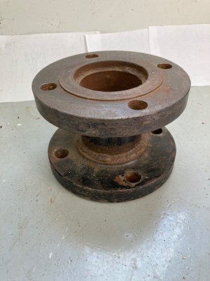
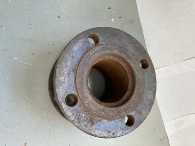
Here is what I have for the riser. Got it at a local junk yard for perhaps 20 cents a pound. It is 7-1/2 inches in diameter (near same as mill column) x 5 inches tall. The flanges are 7/8 inch thick, and the center is 3 inch x 1/4 inch wall pipe. Thinking of welding at least three 3/8 thick gussets between the two flanges and to the center pipe, and then let it sit in the barn for at least a year. A friend told me I would have better success getting the two faces parallel if the second face was faced on a surface grinder or a mill. Any suggestions???Thanks for your response and info. If I can learn how to use my wife's smart phone I may post a picture of what I have to attempt to make the riser from. Your rpm reduction reminded me of what I did with one of my drill presses. I addesd a jack shaft pulley in the middle and later obtained a 825 RPM motor. The arrangement reduced the spindle RPM to approx 135 RPM according to an online calculator.
Attachments
- Joined
- Jan 20, 2016
- Messages
- 173
I hope you misread your rule for that pipe wall thickness? Would be best if that was more than 1/4 wall thickness, as all of the milling loads are cantilevered quite a bit with a 3" OD pipe diameter riser to react the forces (as opposed to a 7-8 diameter riser).
Welding in the 6 gussets will help with the small diameter riser and the minimal wall thickness. After welding them in, I do not see much advantage to letting it sit for a year before final machining. You have to machine the top/bottom flanges of your weldment to match your mill anyway.
Not sure what equipment you have to machine the steps in the flanges, but you pretty much have 2 choices: a. milling machine AND rotary table, or b. lathe. Either way, when you machine the first flange recess or boss, the entire surface will be square/flat, so when you turn it over to do the other flange end it should not be out by hardly anything to worry about.
I measured the flange diameters on mine when I had it all apart after I first bought the machine. My flange outer diameters are 7.800, and the inner locating/rotating flanges are 4.720 (your machine will be different). The lower casting on mine is recessed, with the upper casting flange boss sticking out .250. If yours is same construction, the lower flange on your riser would need to stick out and the upper end would need a spot-face/recess.
As Bruce said, a .010 extra clearance on those flange fits is not going to hurt anything.
My approach is going to be a bit different than a solid 5" riser. I will be 5" overall, but with a 2" high x 6" wide x 12" long double dovetailed bar in the middle. This allows for the head to be moved out/back to reach every part of the table/part. I know that will take some of my rigidity away, but hoping that will be minimal compared to the greatly added flexibility of the fore/aft Bridgport like movement. Might be hard to see/understand, but it will look like this. Loosen 2 locking handles on top and bottom of the dovetailed bar, and slide the head where you want it, tighten 4 locking handles and start machining. The pink part sticking out the right side is just a rod to help slide the dovetailed bar. To make the dovetail milling in the top/bottom riser sections easier, the riser top/bottom will be hex shaped at dovetail end and round where it attaches to the machine.
- Joined
- Mar 19, 2022
- Messages
- 10
Very nice write up on your extensive project! I have an Enco mill that I bought new in 2001 that looks identical to your project mill. I don't use it much anymore and was getting ready to sell it to a young man that is a millwright. I went to set it up with an endmill and no matter which collet I use I can't seem to get the collet to pull in tight to the end mill. I was wondering if you could share some additional info on the quill rebuild you did? I notice that my collets are getting a little gouging on the keyway a couple inches from the top. Could the spindle set screw have loosened up? Do I need a new spindle? Thanks for any advice you can offer.
Mark Early
Mark Early
- Joined
- Jan 1, 2018
- Messages
- 1,156
Very nice write up on your extensive project! I have an Enco mill that I bought new in 2001 that looks identical to your project mill. I don't use it much anymore and was getting ready to sell it to a young man that is a millwright. I went to set it up with an endmill and no matter which collet I use I can't seem to get the collet to pull in tight to the end mill. I was wondering if you could share some additional info on the quill rebuild you did? I notice that my collets are getting a little gouging on the keyway a couple inches from the top. Could the spindle set screw have loosened up? Do I need a new spindle? Thanks for any advice you can offer.
Mark Early
I would first take a look at the draw bar. I doubt it is the problem but it is really easy to remove and check.
I would then put a camera/cell phone camera on the table and point it directly up the spindle and take a picture. You will, of course, need something to light the inside of the spindle while taking a picture. I think a good picture of the inside of the spindle will show you what you need to do next.
- Joined
- Mar 19, 2022
- Messages
- 10
I will give that a try, thanks. Also, I received the instructions to take everything apart from Grizzly. Enco doesn't really support this machine any more, but the Grizzly looks like the same machine with some improvements over the years.I would first take a look at the draw bar. I doubt it is the problem but it is really easy to remove and check.
I would then put a camera/cell phone camera on the table and point it directly up the spindle and take a picture. You will, of course, need something to light the inside of the spindle while taking a picture. I think a good picture of the inside of the spindle will show you what you need to do next.
- Joined
- Mar 19, 2022
- Messages
- 10
Hi Mike,
Here is a photo of the machine and a look up from the bottom. My guess is the set screw in the spindle is protruding out too far? What do you think?
Mark
Here is a photo of the machine and a look up from the bottom. My guess is the set screw in the spindle is protruding out too far? What do you think?
Mark