- Joined
- Jul 31, 2020
- Messages
- 765
The small 7 by 10/12/14/16 lathes have a very light carriage. Often when facing or parting they want to shift. This can result in facing and parting operations which are not entirely flat. I had resorted to stiffly holding the carriage wheel while cranking in the crossfeed; this was less than ideal. Certainly you can put the feed in neutral, and then lock your half nuts to hold the position, but for a precise cut, you would have to rotate the feed thread first to get it in exactly the right position first.
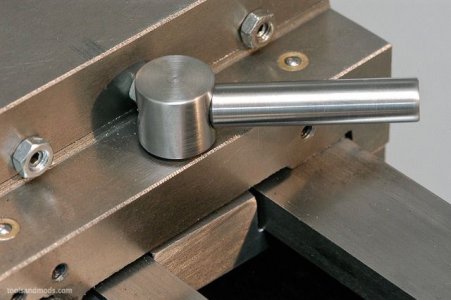
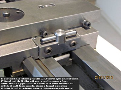
LMS sells a pre-made carriage lock (for those who have not yet purchased a mill to make your own). It bolts onto the lathe via the two screw holes which exist (in most of the current mini-lathes) for bolting on the follower rest. It locks VERY securely, no complaints in that department.
When in the unlocked position the lever is entirely out of the way of everything. It creates no limitations on what can reasonably be machined. The lever rotates clockwise to lock. As such, depending on the thickness of your way stock, it may be in full lock at a position which is not entirely clockwise. You can pop out and rotate the hex nut on the bottom, and the put it back in slightly rotated to get a more ideal "locked" position. If not done, then there is the risk the handle, in the lock position, could strike your outside jaws on a 4 inch or larger chuck.
With the lever in the least favorable position, (facing straight toward the chuck), there is roughly 2 inches of clearance. Once again, not a problem with a 3 inch chuck or 3 inch part being machined. It becomes questionable with a 4 inch part or chuck, and should be measured first. It could become dramatic with a larger chuck or part.
*******Edit update: HMan and WobblyHand pointed out the locking handle is spring loaded and can be lifted up and rotated out of the way of the chuck/work, and dropped back in to a different position on a spline. This move the handle to a nicely tucked away position. ******
In the case of the sample on hand, it locks well past the center line, and gives a more generous clearance (between the end of the lever and the centerline of the chuck) of about 2.5 inches. It would "likely" clear a 5 inch chuck body, but not the jaws if they are extended past the edge of the chuck body. This is assuming you are working VERY close to the chuck.
I considered popping out the hex nut on the bottom, and rotating it one face, but realized it would not be in full-lock when rotated full clockwise; so I lived with the fact it sticks out towards the chuck a bit in the locked position.
Now to state something obvious. The lever and bolt can be replaced with a washer and cap screw; this will eliminate all of the above risks, but it will not be as quick and easy to use. It would have the merit of never creating a potential clearance issue (when locked, or when spinning swarf potentially snags the handle).
The pictures:
1. Bolted in place, red box defining the carriage lock. It is in the Unlocked position.
2. Carriage lock in the Locked position
3. Lever shown in worst-case position for clearance. There is about 2 inches of space between the chuck center line and the top of the lever.
4. Lever shown in the locking position on my lathe. There is roughly 2.5 inches of space between the chuck center line and the top of the lever.
Last edited:


 .
.