4th Axis Build

I took a look at my Tormach 6" RT. It is a motorized Phase II as near as I can tell. I see no evidence of a thrust bearing in the parts diagram.

I have never put it through its paces and now you have me wondering if there may be a problem there as well.
 
Bob, yours may be designed as a motorized table from the get go. My Vertex has an odd arrangement, one end of the shaft is a hardened steel boss contacting on end of the cast iron sleeve. Actually that is a pretty good bearing. The other end consists of a threaded collar and a wave washer to set the end preload. The wave washer is captured between the collar and the cast iron sleeve and acts as the bearing. In this case a wave washer does not make a good bearing, it was starting to gall a bit. It could have been a lack of lubrication, but it's not a good system for high rotational speeds.

EDIT: I looked at the Tormach documents, their super spacer is a Vertex or a clone. It is built identical to mine. The exploded view is incorrect, it shows the sleeve (item 29) in the wrong assembly order, but item 27 is the wave washer in mine, what they are calling a spacer in the parts list. I don't know about your RT, but I could see a problem with their super spacer.
 
Last edited:
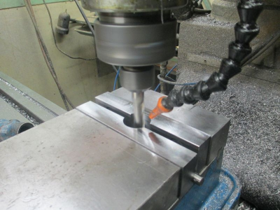
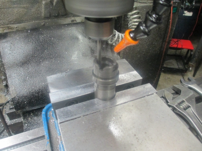
The final step in the process is to pocket the cast iron sleeve for the thrust bearings. The worm shaft must be maintained in the same position as original so the sleeve needs to be pocketed to the thickness of the thrust bearing.

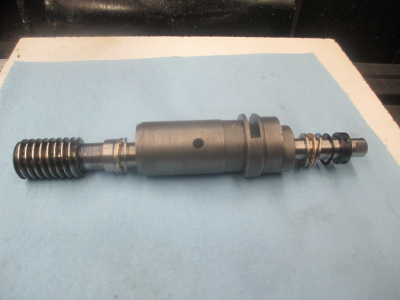
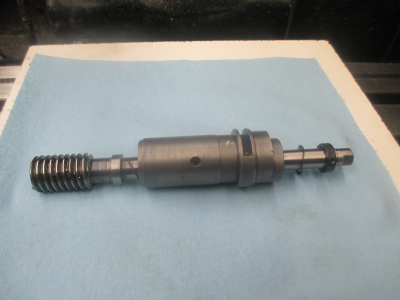
This is the original assembly. The boss just to the right of the worm gear contacted the end of the sleeve as the bearing, and on the other end the ‘’bearing’’ surface is the wave washer that was in contact with the other end of the sleeve. Probably OK for hand operation, but not adequate for powered operation.
upload_2015-12-10_16-46-0.png

Here is the assembly with the new thrust bearings, less the balls. Where is UPS?????:cautious:

upload_2015-12-10_16-46-19.png

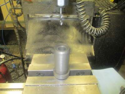
The sleeve setup and ready for pocketing on the worm gear end. The sleeve is held in a round pocket I already had machined into the vice soft jaws for another project. Soft jaws are really handy to have around and easy to make. They allow all kinds of quick fixturing for lots of projects. I normally just leave them in place and use them just like hard jaws until I need to change them because I have modified them to the point they are no longer useful for anything. Just waiting on the bearings to arrive, where’s UPS????????:confused:

upload_2015-12-10_16-46-57.png

upload_2015-12-10_16-47-26.png


UPS finally got here!!!!:)
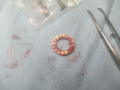
One bearing with the balls loaded and greased up.
upload_2015-12-10_16-47-48.png

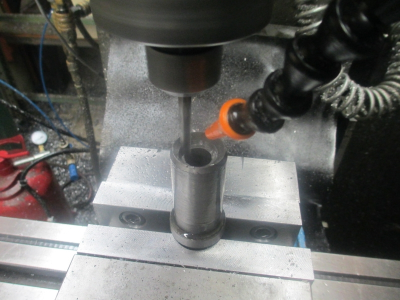
After assembling the bearings, I measured the thickness and found that rather than 4mm they were 4.35 mm, so the pocket needs to be 0.171 deep.

Pocketing the worm gear end of the sleeve
upload_2015-12-10_16-48-20.png

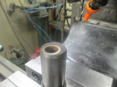
And the bearing in place.

upload_2015-12-10_16-48-39.png

And pocketing the other end

upload_2015-12-10_16-48-56.png

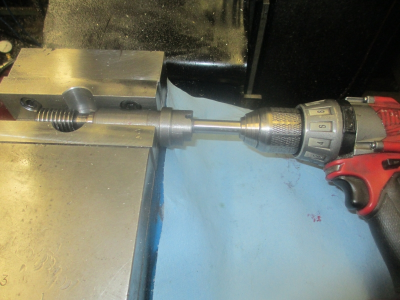
Running in the assembly. This consisted of over tightening the nut and running until the bearings got warm, rest a while, tighten a bit more, run again, rinse repeat until I’m happy with the way it feels. Then back off the nut and bring it back up to what I felt was a proper torque on a 6 inch crescent wrench. With the balls at about a RC62 and the races at about a RC35 hardness this exercise conformed the ball tracks to the balls for a nice fitup. The thickness of the thrust bearing probably changed a bit during the run in operation, but it will be close enough.
upload_2015-12-10_16-49-12.png


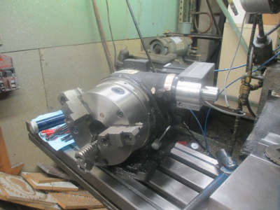
And reassembled. I ran it for about a half hour and it’s nice and smooth, with none of the problems that I experienced before the thrust bearing mod. Before I could easily stop the chuck with my hand and stall the motor. Now I am not able to stall it at all.:) I’m going to call this a success.:grin: :encourage: Now I can get on with my other projects!
upload_2015-12-10_16-49-44.png
 
Jim
Beautiful and well executed again. You da man. I've made nylon thrust washers before, but thrust ball bearings? WOW!

CHuck the grumpy old guy.
 
neat! So I'm guessing helical gears would be somewhat trivial to make with this?
 
Matt, I would say it might be possible to make a helical gear on this setup. Trivial is not the word I would use:) Just thinking about the g-code makes my head hurt. However I did cut a helix as a test when setting up.
 
yeah, perhaps I bandied the word trivial around a bit too much there :D CNC can appear simple to those who know nothing about it, like magic!
 
Matt, I would say it might be possible to make a helical gear on this setup. Trivial is not the word I would use:) Just thinking about the g-code makes my head hurt. However I did cut a helix as a test when setting up.
All you have to do is hold the drawing up in front of the monitor on said machine and it'll program itself - won't it? :grin:
I have actually 'endured' people who believed that with all their hearts and minds.
Computers are a great tool, but some still require programming time...
 
Just read your post. You do amazing work. Thanks so much for posting and passing on all the great info there in. Mike
 
Back
Top