- Joined
- Nov 27, 2022
- Messages
- 108
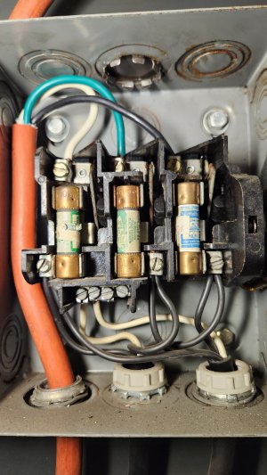
Hello all. I'm looking for some clarification on some wiring. I know explaining wiring and electrical can be tricky but here it is. I got a new mill with a 3 phase motor and coolant pump. The previous owner was running a static converter. I will be using a rotary. The enclosure on the back is a square D brand, 3 phase disconnect. The picture shows how the previous owner has it wired. The three legs, seen on the top connection, are from the static converter. Just 3 wires. On the bottom right, you see the connections going out to the motor and pump. Each has 3 legs and a white wire going to a bus bar. Is that for ground/earth?
My rotary has the three legs and a ground/earth on the discharge side. Do I connect the ground/earth to the bus bar? Thanks in advance.
M. Noob
My rotary has the three legs and a ground/earth on the discharge side. Do I connect the ground/earth to the bus bar? Thanks in advance.
M. Noob