3-2-1 blocks, parallels, and v blocks, oh my! How do you secure your milling workpiece safely and effectively?

A screwless/toolmakers/grinding vise, small enough to fit your mill and a v-block would be my choice for your operation.

I run into the same problems you are with my machines, I have a mill/drill, and everyone thinks a 6" Kurt vise is the only thing that will hold your work piece.
 
I'm a relative newbie myself, albeit with a few decades of hobby woodworking to draw on. I thought I had my clamping needs pretty much covered until yesterday - needed to reduce the diameter of a T-shaped wood-lathe toolrest's post from 3/4" to 1/2". Both arm and rest were eBay finds, and the arm's hole was too small for the rest. Why it's being mounted on a metalworking lathe is a story for another day.
The finished product:
View attachment 432021
As you can see in the pic above, the rest's "T" arm was far too large for the shaft to be turned axially in that silly little lathe o' mine. My first thought had been to mount the T onto the lathe's carriage to feed the shaft horizontally past a boring head to shave it down. No luck with that, so next stop was a mill/rotary table setup: One V block, two clamping kits (mill bed + rotary table), some scrap brass and aluminum, a couple of parallels, a pocket rule acting as a shim, a handful of nuts, bolts, and washers landed me here. It literally made me laugh, hence the picture:
View attachment 432022
Absolutely ludicrous - but I was able to hang my weight off of the clamped part in any direction without it shifting. Upper right in the photo above is a roughing mill against the shaft being being turned down.
Fresh out of that setup, with a few lingering chips:
View attachment 432008
Lessons learned along the way: Need more threaded rod and nuts for my rotary table. Need a variety of shim stock. Need to go slowly, and stop and step back/assess often. Since yesterday I've thought of about six other approaches, including milling a one-off clamping fixture to match the angle of the T arm that bolted directly down to the rotary table, but this got it done.

I think Chipper 5783 nailed it, "Start with a good quality heavy milling vise and a clamp set. Then make and/purchase additional clamping devices - the additional items will go on indefinitely, so buy or make whatever you need as the task determines." (and have fun along the way).
That is nice work, however your RT is bigger than his whole machine.
 
Think a screwless vise can be found as small as 1" jaws. https://www.ebay.com/itm/2850925264...kmuI7qMrBZvhJ7DAlbVcoaw9dXnM|tkp:BFBMyLCYq7Jh
It's funny though, because it is called a screwless vise, but that sure looks like (and it is) a screw to me!
The problem with this is it may still be hard for you to clamp down to your machine. I can't get a sense from the picture of the vise how big it is.

Here's an offbeat idea, use an OXA or AXA tool holder to clamp your stuff. https://www.ebay.com/itm/3741438692...Ka2Xhq4Sf31HOIgriPJ7G76fM=|tkp:Bk9SR9bZ7auyYQ Sure the clamping range is limited to a 1/2" or so, but maybe you could use one. I have used a tool holder to hold a micrometer before. I just put a thin piece of metal between the screws and the micrometer so the mic won't get marked up. Tool holders often aren't hardened and you could drill it or clamp it to your machine. You might be able to use toolmakers clamps for some setups. They aren't too expensive and can sometimes save the day. https://www.ebay.com/itm/3335299887...TbjYLvrGlQkKH3D+ZkQ53qOC8=|tkp:Bk9SR4Ta4KuyYQ

We often repurpose things to clamp stuff. Indeed, just holding the piece is most of the problem. It's common to spend a day or more, figuring out how the hold something, and then make that something, which might take a day or so, so that we can actually machine something. I had to make a split mandrel to hold a back flow valve. There was no other way to hold the piece.
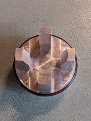
Here's the side I needed to hold on to. Those metal ears sticking up are tapered and not straight. This was my practice piece. I made it out of aluminum.
PXL_20220611_182555942.jpg
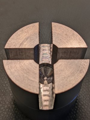
I made four pieces that clamp the four vertical walls of the ears. The next picture is of the mandrel before it became multiple pieces.
PXL_20220426_223020563.jpg
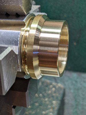
Here is the final piece in the lathe (brass) with the split mandrel. Was pretty easy once I knew how to do things...
PXL_20220504_154022617.jpg
If you look carefully you can see three out of the four quadrants of the split mandrel. One goes on each jaw of the chuck. Took me a couple of days to figure this out, for maybe 20 minutes of machining the brass. Took me two aluminum prototypes, had to make my own o-ring tool out of High Speed Steel, and making that split mandrel to finish the brass (and final) piece. But the back flow valve has been in service this whole past year, so it has all been worth it.

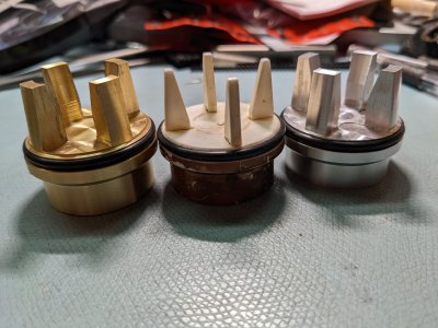
Final picture: the three little pigs :) The final brass piece on the left, the cheap failing plastic piece I was attempting to duplicate in the middle, and the second aluminum prototype on the right. My second aluminum prototype was OK, except it was slightly too short. My first aluminum prototype was just awful, I made a lot of errors on it, including the taper angle of the ears. The first prototype is in my hall of shame...
PXL_20220506_002016239.jpg
Now a person with a lot of machining experience could just bang this out. Me, I'm was learning as I was going along, so it took me three weeks.
 
Back
Top