

- Joined
- Feb 25, 2021
- Messages
- 3,138
Another photo bomb.
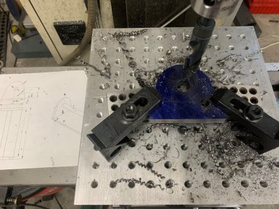
Made the base for it today. Started by one of those fixturing setups that looks like something of a kludge. Rotary table on the mill. Fixture plate on the rotary table. Bandsawed parts stacked together on top of 123 blocks. Edge finder at each layer to keep everything on center of the rotary table. Started by roughing the straight edge along the bottom, as I need those to be the right distance from the 3/4" pivot shaft hole. Then drilled that pivot shaft hole, and then the hole for the locking pin.


Back to the rougher and smoothed out the outer radius, a cosmetic feature.

Then over to the grinder to clean up the rest of the sides, then the upside down handheld belt sander (gee, I need belt grinder) to clean it up a little bit before welding.


My CAD drawings call for a smaller base plate (4" x 8.5"), I went with 6" x 10" to give it a little more stability. I'm using 6" wide material, and welding right at the end is a little more difficult. So there may have been some laziness (fabrication enhancements) to that design mod. I cut a piece of scrap tube and clamped it between these pieces at the desired spacing, and did my best to get it square, tacking it up first and re-checking.

Got the shaft drilled and tapped for 3/8" bolts using the lathe, tapped out the locking pin hole, and put it all together.


Made the base for it today. Started by one of those fixturing setups that looks like something of a kludge. Rotary table on the mill. Fixture plate on the rotary table. Bandsawed parts stacked together on top of 123 blocks. Edge finder at each layer to keep everything on center of the rotary table. Started by roughing the straight edge along the bottom, as I need those to be the right distance from the 3/4" pivot shaft hole. Then drilled that pivot shaft hole, and then the hole for the locking pin.
Back to the rougher and smoothed out the outer radius, a cosmetic feature.
Then over to the grinder to clean up the rest of the sides, then the upside down handheld belt sander (gee, I need belt grinder) to clean it up a little bit before welding.
My CAD drawings call for a smaller base plate (4" x 8.5"), I went with 6" x 10" to give it a little more stability. I'm using 6" wide material, and welding right at the end is a little more difficult. So there may have been some laziness (fabrication enhancements) to that design mod. I cut a piece of scrap tube and clamped it between these pieces at the desired spacing, and did my best to get it square, tacking it up first and re-checking.
Got the shaft drilled and tapped for 3/8" bolts using the lathe, tapped out the locking pin hole, and put it all together.
Attachments
Last edited:

