Well I didn't do anything near the great projects like in the previous posts,but I did do something to better a tool I had. I have the A2Z size QCTP.My cut-off blade kept jumping out of the tool holder when I would push it a little too hard or if I tried cutting an adjacent slot to provide some relief if I were cutting deeper. I got to looking at this holder and decided the bottom lip that holds the blade was too small. So what I did today was to mill the slot a little deeper,thereby providing more lip for the blade to hold on to. Worked!!  )
)
-
Welcome back Guest! Did you know you can mentor other members here at H-M? If not, please check out our Relaunch of Hobby Machinist Mentoring Program!
- Forums
- THE PROJECTS AREA
- PROJECT OF THE DAY --- WHAT DID YOU DO IN YOUR SHOP TODAY?
- Project of the Day Mega-Thread Archives
You are using an out of date browser. It may not display this or other websites correctly.
You should upgrade or use an alternative browser.
You should upgrade or use an alternative browser.
2014 POTD Thread Archive
- Thread starter Smudgemo
- Start date
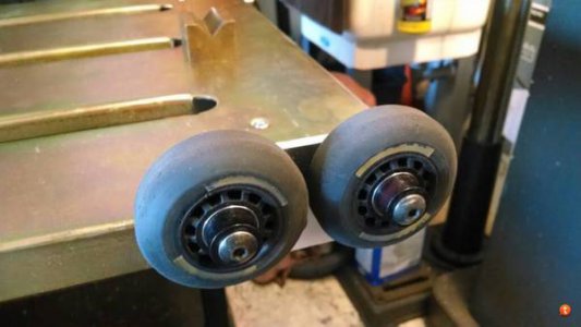
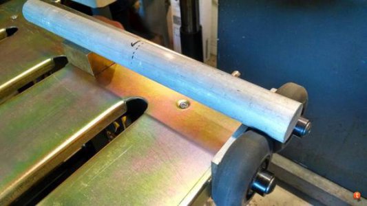
What do you do with old rollerblade wheels, scrap aluminum and a new welding table? Make a set of rollers for welding around tubing of course....
<snip some pics>
I hope the brass v-block will give a decent ground path....
That's just really slick, I like it! And, yeah, I don't think you've gotta worry about a ground path.
Good job!
- Joined
- Apr 8, 2013
- Messages
- 2,007
I needed to machine the fuel rails on my boat engines. Because of their oddball shape my only option for turning them was to make a fixture out of some 3 inch steel pipe with spider bolts at each end. (just a lathe, no mill) I dug out my steady rest but the fingers were so long it would only go up to about 2 inches and I needed 3 1/2 minimum. I didn't have a metric tap so I made new fingers and threaded shafts using a 3/8 16 thread.
Milling the slot on the new fingers
Old vs new fingers
Finished product
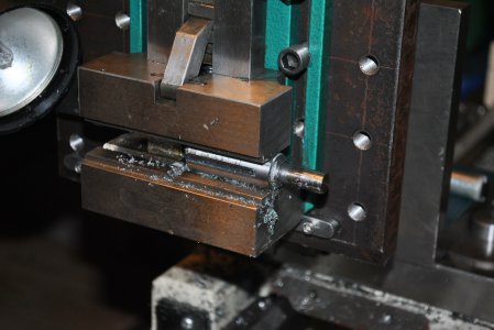
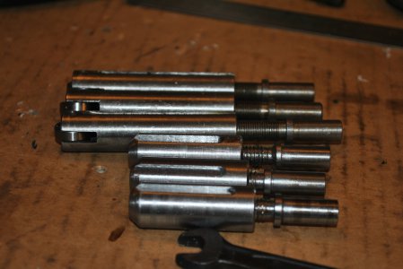
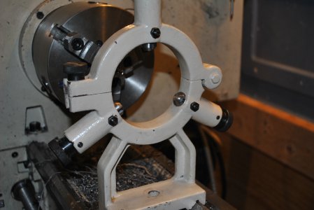
Milling the slot on the new fingers
Old vs new fingers
Finished product


Last edited:
- Joined
- Feb 8, 2014
- Messages
- 11,176
I'm still working on my z-axis CNC conversion. Here are a few more parts I built in the last few days.
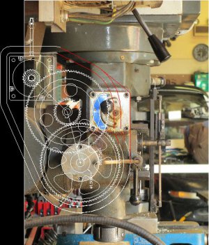
Here is the concept drawing to help put this in perspective
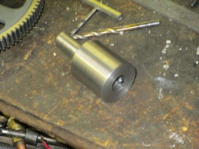
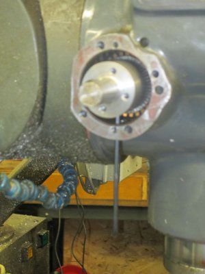
Quill Shaft Adapter. This was made in 2 pieces so I could key the barrel, the shaft screws into the end. I have a 1 inch -32 tap from another project so I used that to thread the barrel,and single-pointed the shaft.
Quill shaft adapter installed. I drilled and tapped a couple of 1/4-20 holes in the mill head to access the set screws in the adapter.
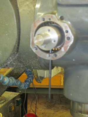
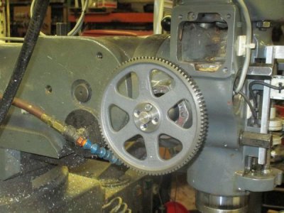
With the bull gear in place. The gear is free to turn on the shaft, the drive is through the 4 soft machine screws. The idea behind this is that the soft screws will shear at about 120% of max design torque, hopefully saving the rest of the hardware. I hope I did the shear calculations correctly.
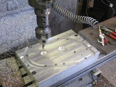
The gear case cover in process
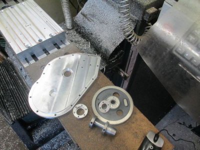
The rest of the parts, Intermediate gear assembly, spacer goes between the gears, the intermediate gear shaft and engage/disengage cam, outboard motor shaft support bearing housing, and the gear case cover.
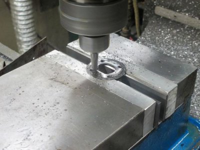
Milling the gear spacer
A rough assembly view.
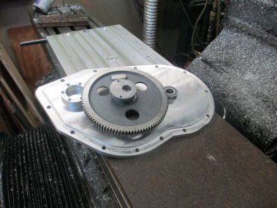
The big block of aluminum bolted to the table will become the gear case tomorrow, it's in there somewhere I just need to dig it out.
To see more of the project at http://www.dawsoncontrols.com/millupgrade.html and at http://www.hobby-machinist.com/showthread.php?t=21060
I'll add a bit more both to my web site and my thread here.
Here is the concept drawing to help put this in perspective

Quill Shaft Adapter. This was made in 2 pieces so I could key the barrel, the shaft screws into the end. I have a 1 inch -32 tap from another project so I used that to thread the barrel,and single-pointed the shaft.

Quill shaft adapter installed. I drilled and tapped a couple of 1/4-20 holes in the mill head to access the set screws in the adapter.

With the bull gear in place. The gear is free to turn on the shaft, the drive is through the 4 soft machine screws. The idea behind this is that the soft screws will shear at about 120% of max design torque, hopefully saving the rest of the hardware. I hope I did the shear calculations correctly.

The gear case cover in process

The rest of the parts, Intermediate gear assembly, spacer goes between the gears, the intermediate gear shaft and engage/disengage cam, outboard motor shaft support bearing housing, and the gear case cover.

Milling the gear spacer

A rough assembly view.

The big block of aluminum bolted to the table will become the gear case tomorrow, it's in there somewhere I just need to dig it out.
To see more of the project at http://www.dawsoncontrols.com/millupgrade.html and at http://www.hobby-machinist.com/showthread.php?t=21060
I'll add a bit more both to my web site and my thread here.

Last edited:
I bolted down my 7x10 lathe onto the top of my new tool cabinet. probably not the best idea, but for a machine this size i think it fine. theres a piece of hardwood between the two to stiffen it up some. now i can get all around it easily, and roll it whereever i want to. i gotta add a light to it yet, and im still trying to find the "sweet spot" adjustment between no play and too stiff on the carriage and dovetails. then i turned down an airline coupler to fit the hose on my bicycle pump, now it has a normal end i can lock onto the valvestem. always hated the original end on it.
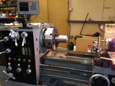
Well I just finished making a 5c collet adapter to fit a #5 morse taper in the headstock of my new lathe.
I had to make the #5 morse taper and machine the center to accept the 5c collet
Also made a drawbar and nut with a centering thrust washer.
The adapter is made of stainless as is the nut and thrust washer
The drawbar is made from a piece of 1" back iron pipe. The OD was 1.315 and the ID was 1.060
The internal thread that attaches to the collet is also custom at 1.240 x20 TPI.
Because my lathe is not a quick change and the change the gearing is a pain, the thread for the drawbar and nut is also 20TPI.
Diameter of 1.310
I will try to attach a couple of photos,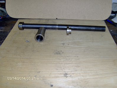


View attachment 72375
Not much of a start but I finally got the stock to make my cross feed bracket. Now to whittle away about 60 percent of it, if I ever get my compound screw fixed. I had to take it to a machine shop because I didn't have enough lathe left to do anything myself.
Jimmy, what kind of lathe is that ??
- Joined
- Dec 17, 2012
- Messages
- 630
I went out first thing and field stripped my lathe and cleaned out everything. Especially the apron that was getting grotty. When I put it back together, I swapped out my QCTP for my little piston type. The threads on the wedge closer on my other one have been acting up and I want to take a look and see what I can do to get it straightened out. It might involve building up a bit of bronze and filing it back. It is nice to have a backup plan.
While I was out there, I went ahead and made a new slitting saw arbor (posted under projects.)
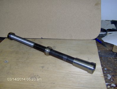
While I was out there, I went ahead and made a new slitting saw arbor (posted under projects.)

