1964 10EE lathe

Man, rabler, your analysis and design direction is excellent. Possibly like you, this project would be a cross section of my professional career, and something that would be exciting to take on, and I applaud you for it.

Please continue showing us your progress. I suspect for 10EEs, the price is about to go up and the availability about to go down, with all the drooling going on out here in cyberspace.
Yes, this has the makings of one of those HM historic go to threads! No pressure.
 
I've been alternately working on the electronics and the mechanical parts of the 10EE. I jump back and forth depending on what mood I'm in, and what I have on hand. Often something ends up hold while waiting for parts, often via mail-order, or just waiting for a coat of paint to dry enough for a part to be reasonable to handle which often takes a few days. I'm trying to write this up with some idea of a timeline, without jumping back and forth quite as often as I do between various aspects of this project.

I got the body of the lathe painted, and put it together a bit to just keep the pieces from creating too much clutter. It's pretty dusty here (some woodworking/sanding going on). Maybe not the best angle for a photo but I'm not willing to move it around to get it's "best side". Pictures probably make the paint look a bit better than reality but it certainly looks better than the original worn off paint.

IMG_3644.JPG

I've gone over the gearbox. At this point I'm going to put it back together without completely disassembling it. Other than a needing really good cleaning the gearbox seems to work well. I took the apron side faceplate off as the bearings for the leadscrew and feed rod felt a bit rough and I wanted to replace them. I also needed to drill out one of the taper pins to separate the feed rod from that faceplate. I had tried to pull the faceplate off without removing the gearbox from the lathe, but the two capscrew holes on the right as shown here are not accessible with the gearbox in the lathe, as it sits partially recessed into the bed under the headstock.
IMG_3567.JPGIMG_3569.JPG

Each of the two rods (leadscrew and feed rod) uses two opposing taper bearings to eliminate any play in those.
Here's the picture of the gearbox sitting on the bench. I used diesel fuel in a 1 gallon garden sprayer to thoroughly flush the gearbox and wash all the residue out from the bottom of the inside.
IMG_3572.JPGIMG_3649.JPG


I've put a first coat of paint on the face of the gearbox, and I bought some 1/32 gasket material from McMaster to make replace gaskets. These gaskets tend to leak and can't be replaced without pulling the gearbox off.

Note that I didn't take all of the control handles off, while that would make repainting easier I opted to just do what I can without stripping it all down. My goal is to have a functional lathe with a bit of attention to cosmetics, not to make a prize winning showpiece. I will be putting a second coat of paint on the gearbox, as I think that'll last longer. The lathe body has two coats also. The second picture below shows the faceplate reassembled to the body of the gearbox, with the leadscrew and feed rod bushings installed with the new bearings. The third and last picture is the backplate of the gearbox re-installed with a new gasket, apparently this is a very common source of leaking on these lathes, and frustrating as pulling the gearbox is not trivial.

IMG_3645.JPGIMG_3647.JPGIMG_3646.JPG
 
Last edited:
While I haven't finished painting and remounting the gearbox, I went ahead and pulled the apron apart. With all the levers/controls it is hard to do a good job of painting without disassembly, but more importantly, the apron on most Monarch lathes contains an oil pump which lubricates the apron, as well as the carriage, bed ways, and cross slide. Cleaning out that oil pump, and the corresponding copper lines to everything is necessary as they often get plugged up over the years.

IMG_3515.JPGIMG_3516.JPG

It seems to worked best to start from the headstock side of the apron, taking the shafts and components out from that end and working toward the tailstock end. These are from my disassembly notes pictures sequence. so they're not the best framed pictures, but the sequence of pictures, and the placement of the parts in the pictures, helps me figure out how to put it all back together. I also use a lot of ziplock bags to keep small parts together, labeled and numbered in sequence.
IMG_3527.JPGIMG_3518.JPG

Fortunately on this apron the whole bottom comes off too. My CK that I had previously redone the apron did not have a removeable bottom, it was all one casting. Obviously this was a real mess. Note that you can see the oil pump on the bottom of the apron. It sits in the bottom so it was trying to pump up oil through this mess. (And probably failing).
IMG_3543.JPG
 

Attachments

  • IMG_3540.JPG
    IMG_3540.JPG
    1.9 MB · Views: 18
Karl,
Another way to look at that is torque at 60Hz. Since HP = torque * RPM * (conversion constant):
A 2 pole motor produce 1 HP spins twice as fast as a 4 pole 1 HP motor. The two pole motor has 1/2 the torque.
But you can put a 2:1 pulley on the 2 pole motor and get the same RPM and torque as the 4 pole motor. Ignoring pulley loss you haven't really gained anything. It's really just a matter of matching the RPM of the motor you're replacing to avoid having to add that extra 2:1 pulley.

A 6 pole motor is a close match to the original Monarch torque curve. And by going from the typical 3 HP to 7.5 HP you've thrown in a good bit of extra torque to make up for the fact that AC motors don't usually deliver good torque at really low RPM. With the back gear you are set. I think I already alluded to the fact that If I were starting over I would go this route.
Question for Rabler or Karl.
I'm resurrecting a small radial arm drill. The spindle has a 1.5HP 3 phase motor (the elevate motor is a small 3 phase motor). Though I have 3 phase in my shop (PhasePerfect) my intent is to bring 3 phase to the drill, for the elevate motor via conventional contactors and to power a VFD for the spindle. The rational for the VFD is two fold: 1. I like some easy speed range on a drill press (I have a good sized post drill with a VFD and I like it) 2. to increase the speed range. The drill has a 3 speed gear box, I'm keeping it (to help with the turn down issues you described with a VFD). The spindle motor is a 2 speed motor (830 & 1630) - seems like a lot of slip for 8 pole - 4 pole 60 hz motor. Per the machine name plate, right now I have 6 speeds from 130-900 rpm. From the motor's point of view, do you see any issue running it to 3600rpm (about 125Hz on the Hi setting)?
The two issues when using a VFD on a motor are cooling, and some weird arcing effects associated with the high switching frequency coming out of the VFD.

Cooling is only a problem if you push the lower end because the motor fan is also turning slower. For a higher speed (>60Hz) it isn't a problem. You might shorten the life of your bearings some by cranking up higher speeds, and I'd probably consider putting new bearings in the motor if there is any doubt to their condition.

The high switching frequency issues can be mitigated to some extent by keeping the wiring from VFD to motor as short as possible, and by programming the VFD to a lower switching frequency. IIRC, my TECO VFD for example goes up to 15KHz and uses that as a default, I dropped it to 11KHz. Going too low tends to produce an audible whine or high pitched hum, depending on your hearing, so if it is annoying trying bumping the frequency up a bit. Note that switching frequency is NOT the same as the motor speed frequency, it has to do with how fast the VFD pulses the power on and off to try to emulate a sine wave. "Inverter" rated motors are designed with this issue in mind. A lot of people are using non-inverter rated motors successfully. Might be shortening the motor life to some extent? But if your old motor dies next week, for the average end user it is hard to tell if the VFD killed it or it was just old.
Thank you for the tips. I don't see demanding much torque (50 Hz is still a decent motor speed) and I'd have a drill speed of about 110rpm. I can't think of many applications where I'd need good torque at significantly lower speed. If it seems the case, then a RAD is probably not the right machine for the task. I've heard that about keeping the motor leads short (in this case they'll be about 2' long).

The previously mentioned post drill is using a non-inverter rated motor, the leads are short, it has been working great (in fairness, it really doesn't see much use - it it lasts another 12 operating hours, that is probably more than I'll use it in the next 15 years).
 
The casting for the apron has been painted. Some cleanup of overpaint is still needed here. Also, here is a better picture of the control knob mounting arrangement I built.

A9D7490A-8FDE-4388-B03E-1BE27A0E9DDB.jpeg725EDE43-EE05-4D48-8C30-C048D02C062B.jpeg
 
I was working on the electronics side of this, got the motor hooked up to the control board to do some testing and code debugging. Had to fix a few code issues, but the DC motor turns both forward and reverse. But it turns pretty rough, bad enough that I'm not going to be able to do the needed tuning on the two Parker DC power supplies.

For those into technical details, the Parker units are meant for powering DC motors, so they have some control functions built in. Somewhat like a VFD, you give it a low voltage signal which it translate to RPM (armature voltage) for one, and field current for the other. DC motors being somewhat odd, you start out with full field current, and increase the armature voltage to (roughly) increase the RPM. When you reach peak rated voltage on the armature, you are not yet at the motor rated maximum RPM. To increase the RPM further, you decrease the field current. Interestingly, some DC motors, especially if unloaded, will self-destruct in overspeed if you decrease the field current to zero. Which could happen if the field circuit or wiring fails.

The Parker 514 is a full armature controller, and understands how to monitor the current and voltage of the armature and control it appropriately to get desired RPM even with a changing load, and will provide braking (allowing current to flow back to the line) if the RPM gets dialed back. It does take some tuning, it is essentially an analog PID controller, so various gain parameters need to be set. But it doesn't know how to coordintate this with the 507 field controller. Some people just use two separate inputs (pots) to control them separately, and it is up to the operator to know how to fiddle with two knobs to get the desired RPM.

IMG_3668c.jpg

I decided to build a digital controller front end that uses one knob to set the RPM I want, and that microcontroller figures out how to get there from where ever it is now. All good in theory, but of course now three devices (microcontroller and two Parker DC supplies) that need to coordinate correctly. Or really, I have to program the microcontroller correctly and tune the Parker's correctly. But wait, there is a fourth player. The motor itself. This motor needs some help, as the commutator is not in great shape. With a bad commutator and brushes making less than good contact, the motor struggles.

So the DC motor needs to come apart. Sort of thought that would be a good idea anyway, new bearings and brushes was on the list. Additionally, I'm going to need to turn the commutator, as in put in on a lathe and take a couple thou off to get a nice, round, even surface for best brush contact and life. After turning the commutator, the mica insulation between the commutator bars needs to be undercut a bit, as otherwise the mica will not allow good brush to copper contact.

IMG_3670.JPG

IMG_3677.JPG

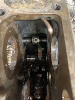
My workbench is a bit full of projects (pieces) so I've decided to get the apron reassembled before tearing into the DC motor. So the apron is going back together. I replaced the bearings that ride on the underside of the ways, and the thrust bearings on either side of the feed worm. The other bearings seem to be in pretty good shape. The pinion gear that rides on the bed rack is a bit more worn then I'd like but it isn't so bad that it won't engage. I replaced the filter on the oil pump and cleaned that out. This apron also has part of the ELSR (electronic lead screw reverse) which is really just a motor shut off. That mechanism had one of the fittings commonly used for grease but intended for oil, so that mechanism was a mess of old solidified grease. Picture is from a day or two ago, it is almost completely back together now, just waiting for a coat of touch up paint to dry enough to move it off the bench. I have the QCGB ready to go back into the lathe too, so need to do that. Shop is getting crowded with parts. Then I'll tackle the motor. Keep your fingers crossed that I'm able to clean up the commutator, and motor in general. Otherwise .... VFD and oversized induction motor will be in this lathe's future.
 
Last edited:
Here’s what the back side of the apron looks like, as well as the pinion gear.
The inner ring of teeth is overcut from cutting the gear teeth. So the teeth right up against the apron aren’t fully cut, I assume that diameter is there to ride on the bearing
.3EA95A04-4A3A-43FB-B54C-FD0EE9AB0B39.jpeg
5CB725E5-1F37-4E89-8708-36558CA8A199.jpeg
 
Waiting on some 5/32 soft copper tubing to replace the oil lines in the apron. Once those show up I'll be able to rehang the apron. Then I get to tackle the DC motor.
 
Back
Top