
Really nice work Jake/David! Another solid plinth fan here. I made one for my Craftsman 12x36 and it was a game changer. I've since upgraded to a Summit 1440B, and intend to do the same for it. While being very rigid at over 3000 pounds, and having a gib lock for the compound, everything moves to some degree, no matter how rigid. I really like the super accurate repeatability it provides when you store tools in the DRO memory. Once you're cutting tools are carefully verified and stored, unless you're working to tolerances less than .001" or so, you don't even need to bother measuring your work other than the occasional confidence check. Makes general machining very fast and convenient.

-
Welcome back Guest! Did you know you can mentor other members here at H-M? If not, please check out our Relaunch of Hobby Machinist Mentoring Program!
You are using an out of date browser. It may not display this or other websites correctly.
You should upgrade or use an alternative browser.
You should upgrade or use an alternative browser.
1340GT/1440GT Solid Tool Post
- Thread starter Jake P
- Start date
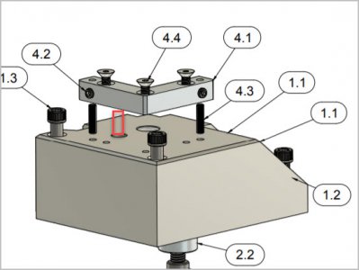
Pardon the dumb question David & Jake. I'm actually just noticing the set screws in part 4.1 the 90-deg bracket for the first time. Duh.
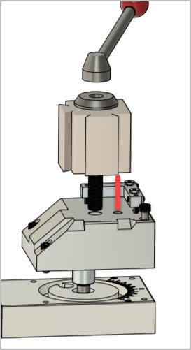
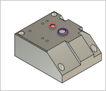
Is the purpose to actually constrain any minor planar TP movement between dowel pin (red) & clamp post (purple) ID/OD gaps? Is the thinking that friction force under the TP via the clamp screw is doing most of the load resistance, or does some of that force translate back to the (relatively small area) set screw points. Not a design criticism, it obviously works. Just trying to understand.
Is the purpose to actually constrain any minor planar TP movement between dowel pin (red) & clamp post (purple) ID/OD gaps? Is the thinking that friction force under the TP via the clamp screw is doing most of the load resistance, or does some of that force translate back to the (relatively small area) set screw points. Not a design criticism, it obviously works. Just trying to understand.
Attachments
- Joined
- Dec 26, 2015
- Messages
- 2,079
It's not a dumb question. And there are several ways to look at this. Keep in mind that my original prototype of this was based on a design by Robin Renzetti, further modified/refined by Stefan Gotteswinter. I recommend you click on their names and that will take you to their videos on YouTube.Pardon the dumb question David & Jake. I'm actually just noticing the set screws in part 4.1 the 90-deg bracket for the first time. Duh.
Is the purpose to actually constrain any minor planar TP movement between dowel pin (red) & clamp post (purple) ID/OD gaps? Is the thinking that friction force under the TP via the clamp screw is doing most of the load resistance, or does some of that force translate back to the (relatively small area) set screw points. Not a design criticism, it obviously works. Just trying to understand.
If you look at what Robin came up with, his design has an L-Shaped anti-rotation device machined into the plinth block itself with two set screws pressing against the QCTP. If you watch his video, Robin discusses the purpose of these two set screws at about 10:20 in the timeline - the gist of which is to put the QCTP into a preload condition against the dowel pins installed (and hidden) between the plinth and the QCTP . Keep in mind that Robin's lathe is a Hardinge, and he routinely works to tolerances of 5 microns - that's 0.0002" - so he is absolutely fanatical about precision. (As you can see later in his video, he even went to the trouble to lap the bottom of the plinth after the set screws were cinched down to eliminate any torsional bending of the plinth's bottom surface).
I thought Robin's idea of the set screws, and preloading the QCTP against the dowel pins made sense. Using the set screws you could dial in the alignment of the QCTP to be absolutely square to the spindle axis which is critical in improving parting operation reliability.
But I was somewhat put off by the complexity of Robin's design - specifically making that corner L-shaped thing part of the plinth block itself.
Then I watched how Stefan took Robin's idea and applied it to his lathe. Instead of making the L-shaped corner element part of the plinth, he made it a separate component that was screwed down and pinned to the plinth. I liked that idea, but Stefan eliminated the set screws, and instead contrived a highly precise method of staking the corner brace down precisely enough that the tool post was exactly square to the spindle axis and at the same time preloaded against the center mounting post so any sloppiness was eliminated. (Stefan at the time was using a Trepan style QCTP, not the Aloris type we're used to). Here is what his design looked like - the corner brace is screwed down to the plinth and then secured with oversize dowel pins pressed into the structure:
What I ended up prototyping was similar to Stefan's idea applied to a Dorian QCTP - separate corner L-bracket, screwed and pinned to the plinth precisely enough to put the QCTP block in tension against the anti-rotation dowel pins.
I have to say, getting that corner L-bracket precisely positioned to put everything into preload and ensure the QCTP was square to the spindle axis was tedious. I consider it dumb luck that I got it staked down successfully the first time. So I started thinking that if I did this again, or suggested someone else implement this, it needed further simplification.
Then Jake called, said he had an Aloris QCTP which was slightly different dimensions than my Dorian, and I thought it was worthwhile coming up with a design that was agnostic as to Dorian or Aloris, and at the same time was less demanding in getting the QCTP aligned precisely and also locked into a preload against the anti-rotation dowel pins. That's what lead to the updated 3D model and drawing you now see and what Jake implemented. Hopefully, it has the same advantages of the Renzetti and Gotteswinter concepts in a package that is easier to machine while at the same time makes the alignment of the QCTP and putting it in tension against the dowel pins something that is done with set (grub) screws instead of ultra precision pin placements.
Now, is it necessary to have a belt-and-suspenders approach that includes both an adjustable corner bracket and employs anti-rotation dowel pins between the QCTP and the plinth? Well, that's a matter of conjecture. Jake and I debated this. I like the idea of putting the QCTP into a preload condition against something to ensure that when the QCTP is installed, you can count on it going back to the exact same alignment and registration on the plinth. Would putting the QCTP in preload against the center locking post be sufficient? Maybe. But adding the dowel pin(s) between the plinth and the QCTP feels to me like a better buttress to preload against than trying to rely on the QCTP center post.
The drawings I posted call out 1/4-28 flat-tipped set screws which I think are robust enough (in conjunction with the dowel pins) to resist the rotational forces, and also finely threaded enough to make dialing in the angular registration straight forward. Does this make sense?
As Paul Harvey would say: "And THAT - is the rest of the story."
Sorry for the long winded tale, but hopefully it answers your question. Sing out if it does not.
David
Good explanation, David. Yes I did see the Robin & Stefan vids back when they came out. I was all hot to build a solid tool post for my 14x40 around that time, gathering info including your rendition. I'll start at the beginning & refresh my brain. I see you've added new projects in your flickr album I'll have to graze upon LOL.